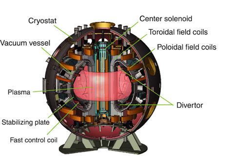
Fig.3-2 Structure of the JT-60SA device
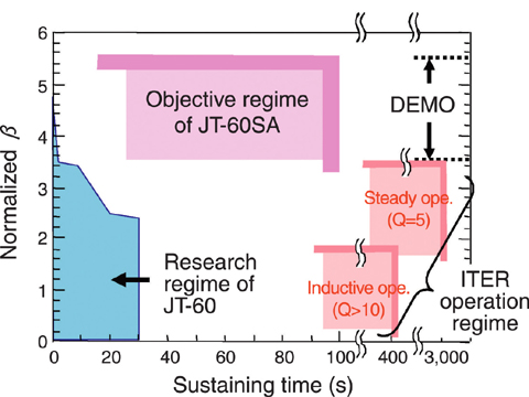
Fig.3-3 Objective regime of the JT-60SA program
The power density of a fusion reactor is roughly proportional to the square of normalized β (βN; index of plasma pressure). High power density operation expected in the DEMO reactor requires stable operation of plasma with normalized βN of 3.5-5.5.
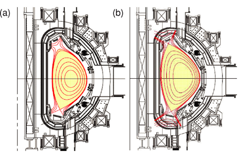
Fig.3-4 Plasma configurations suitable for ITER-supporting and ITER-complementing research
"JT-60SA" is a tokamak-type fusion experimental device with superconducting coils (hereafter SC) (Fig.3-2). This device will be constructed as an updated version of the present "JT-60U" as a joint project of the ITER Satellite Tokamak Program of Japan and Europe and the Japanese National Centralized Tokamak Program (JT-60SA program). The main objectives consist of ITER-supporting research directly contributing to "ITER" and ITER-complementing research for DEMO reactors, executed in parallel with ITER. The latter aims at studying high β (high pressure) plasmas necessary for economically feasible DEMO reactors with high power density, and establishing a method for its steady operation (Fig.3-3).
The conceptual design of JT-60SA has been completed recently after four years of design activities. JT-60SA is capable of sustaining a plasma current of 5.5 MA for 100 s by electromagnetic induction. The SC system consists of the center solenoid with Nb3Sn as in ITER and the toroidal coil and poloidal coils with NbTi, which were determined through optimization for the 5.5 MA operation. Two typical plasma configurations with different cross-sectional shapes are established in one device; an ITER-like configuration with almost the same aspect ratio A (a ratio of major radius to minor radius of a plasma), elongation factor δ and triangularity k as ITER, and a high β oriented configuration with low A, high δ and high κ suitable for studying high pressure plasmas. Upper and lower divertor shapes and the arrangement of poloidal coils were optimized for these configurations (Fig.3-4). Stabilizing plates and fast control coils are installed in the vacuum vessel, to improve the stability of the plasma. The heating power necessary for achieving high temperature and high density break-even class plasmas and steady state high β plasmas has been assessed from simulation results, and the neutral beam injection of 34 MW and the electron cyclotron heating of 7 MW are provided. Since the heat flux to the divertor is estimated to reach 15 MW/m2 with such high power injection, a mono- block-type carbon-fiber- composite divertor with high cooling efficiency has been designed. On the other hand, nuclear heating of the SCs by secondary γ-rays and activation of the device and air (argon) by thermal neutrons must be reduced because these phenomena hinder the operation and maintenance. This is resolved by circulating borated water in the double wall of the vacuum vessel and filling boron-doped concrete in the wall of the cryostat.
The conceptual design was made mainly by JAEA, incorporating requirements of Satellite Tokamak Program to the JT-60SA program, and has been reviewed by Japanese and European experts. The JT-60SA program officially started in June, 2007 as a 10 year program with 7-year construction and 3-year experimental periods.
<Previous: 3 Nuclear Fusion Research and Development | Next: 3-2 >

