Table 2-1 Comparison of main specifications of prototype and commercial fast reactors in Japan
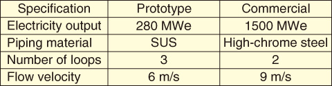
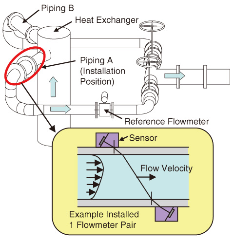
Fig.2-5 Test loop of ultrasonic flowmeter
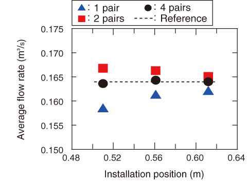
Fig.2-6 Measurement characteristics depending on installation position and number of ultrasonic flowmeters
As one of the fundamental engineering tasks towards commercialization of a fast reactor cycle technology, a flow rate measurement technique for the sodium coolant is developed. The development requirements and investigation results are presented below.
As shown in Table 2-1, because the piping material is a nonmagnetic stainless steel, an electromagnetic flowmeter has been used as the flowmeter in fast reactors that use a liquid metal, such as the prototype reactor “MONJU”. However, because the piping material in a commercial reactor is a high-chrome magnetic steel, which can shorten the required piping length, the electromagnetic flowmeter cannot be applied. In addition, the flow velocity is increased to reduce the loop number and simplify the heat transport systems. Because of the short straight pipes and high velocity, the flowmeter needs to measure a flow that exhibits greater temporospatial fluctuation than before. Because an examination of the flowmeter under fluctuating flow conditions and with high-chrome steel pipes revealed that an ultrasonic flowmeter was most suitable, its applicability was investigated experimentally.
A schematic of the test loop is shown in Fig.2-5. Because the test loop can circulate water at a flow velocity comparable to that in a commercial reactor, the flow condition of a temporospatially fluctuating flow can be simulated. Although the flowmeters are installed in piping A and B at the outlets of a heat exchanger, the measured flow rate should preferably be independent of the installation position to increase the layout design flexibility. Then, the installation position and the number of ultrasonic flowmeters (which corresponds to the measured instantaneous velocity profile in the pipe cross section) were changed, and the flow rate measurement was tested.
A test result is shown in Fig.2-6. For one or two pairs of flowmeters, the measured flow rate varied with the installation positions relative to the heat exchanger outlet. On the other hand, for four pairs of flowmeters installed at intervals of 90° in the circumference angle, the position dependency of the measured flow rate was reduced, and the flow rates were the same as that measured by the reference flowmeter. This result indicates that the ultrasonic flowmeter can be applied to the temporospatially fluctuating flow.
The present study was performed under a contract with Mitsubishi Fast Breeder Reactor (MFBR) Systems, Inc., as part of a study that was entrusted to MFBR Systems, Inc., by the Ministry of Education, Culture, Sports, Science and Technology of Japan (MEXT).

