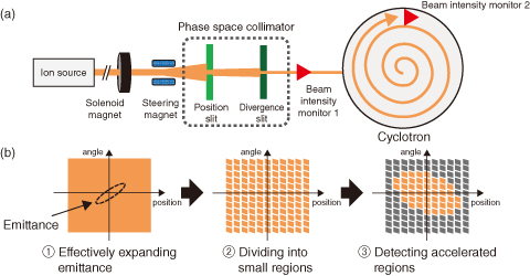
Fig.5-44 (a) Emittance and acceptance measurement system and (b) acceptance measurement procedure
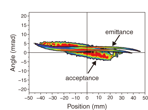
Fig.5-45 Results of emittance and acceptance measurements
The TIARA cyclotron facility produces various types of ion beams for different researches (such as bioscience and material sciences) by changing the ion species in each experiment. Beam injection tuning that maximizes the ratio of the accelerated beam current to the beam current injected into the cyclotron is required to ensure sufficient current for each experiment. The tuning corresponds to the overlapping of emittance (a region occupied by the injected beam) and acceptance (an acceleration region) in phase space. Because any emittance regions outside the acceptance are not accelerated, the emittance must be matched to the acceptance. Although various methods are available for measuring the emittance, no method has been developed for measuring the acceptance of a cyclotron. To fill this gap, we devised a method for measuring the acceptance, and developed a transverse emittance and acceptance measurement system for visualizing the emittance–acceptance relationship.
Figs.5-44(a) and (b) are schematics of the measurement system and procedure, respectively. The acceptance is determined by the following three steps: (1) The beam emittance from the ion source is effectively expanded by solenoid magnets and a steering magnet to ensure sufficient measurement range (Fig.5-44(b)①). (2) The expanded emittance is divided into many small regions by two slits called phase space collimator (Fig.5-44(b)②), and the beamlets with the regions are sequentially injected into the cyclotron. (3) The acceptance is obtained by aggregating the accelerated beamlets detected by beam intensity monitor 2 (Fig.5-44(b)③). The emittance is obtained by measuring the beam intensity of each region divided by the phase space collimator using beam intensity monitor 1.
Fig.5-45 shows the measured emittance and acceptance on a single plot. We succeeded to visualize the relationship between the injected beam emittance and the acceptance of the cyclotron using the system.
On the basis of the results of the emittance and acceptance measurements, we will develop a beam injection tuning system that overlaps the emittance and acceptance to maximize the ratio of the accelerated beam.
<Previous: 5-16 | Next: 6 Nuclear Hydrogen and Heat Application Research >

