Fig.1-37 Analysis model of RPV lower head
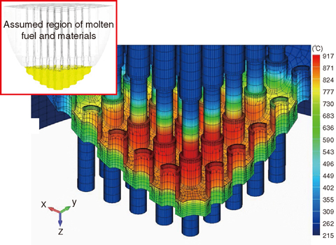
Fig.1-38 An example of the temperature distribution
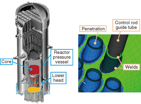
To gain better awareness of the situation within the reactor pressure vessel (RPV) of the TEPCO’s Fukushima Daiichi NPS (1F) and improve the current severe accident (SA) analysis codes, e.g. THALES2 developed by JAEA, we are conducting research and development to assess the rupture behavior of the RPV lower head due to relocation of the molten core. Since simple evaluation methods and models are used for rupture evaluations in the current SA analysis codes, failure time and location obtained from the current codes may include a large uncertainty (scatter). For more accurate evaluations of the rupture behavior of the lower head of boiling water reactors (BWRs) like 1F, it is necessary to develop methods to estimate local failure by considering geometrically complicated structures (Fig.1-37).
In this study, we are developing a coupled analysis method of thermal-hydraulics (TH) and structural analyses, which are to be applied to the behavior of a molten core and to the thermal-elastic-plastic-creep behavior of the structures, respectively. We are also developing methods for evaluating the failure time and locations of the RPV lower head due to creep-deformation.
Fig.1-38 illustrates an example of analysis results obtained by using a three-dimensional (3D) model that considers the penetrations of a BWR (Fig.1-37). As an initial condition, we assumed that 10% of the reactor core has been melted and relocated to the lower head, and that the coolant water in the reactor is completely evaporated. Here, this scenario differs from the accident at 1F. The relocated core is heated by decay heat and the temperature of the lower head also increases. Using the developed failure-evaluation methods considering creep-deformation, we estimated that ruptures would occur at the penetrations because the damage index showed maximal values at those points.
In future, through experiments whose details are described in Topic 1-17, we will improve the failure-evaluation methods and contribute to the estimation of rupture time and the location of RPV in 1F and the improvement of SA analysis codes.

