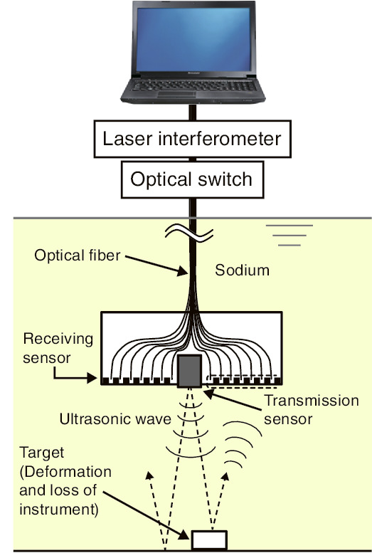
Fig.7-9 Composition of USV
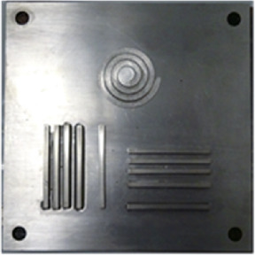
Fig.7-10 Photograph of an imaging target
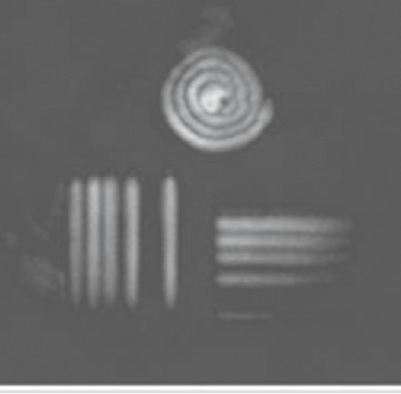
Fig.7-11 Result of an imaging experiment in water
As a fundamental engineering task towards commercialization of fast-reactor-cycle technology, we have developed an under-sodium viewer (USV) for inspection in opaque-liquid-metal coolant.
The USV system will be operated at regular inspection times during commercial use. The USV is required to be able to perform quick inspections in order to conduct an efficient regular inspection. Therefore, we aim to develop a USV that can be used to conduct inspections from a 1–m distance and reduce the measurement time.
Fig.7-9 shows a schematic of the USV. A transmission sensor that includes a piezo element transmits an ultrasonic wave, which is received by receiving sensors located around the transmission sensor. The USV detects the distance from the target using the delay between the transmission and reception times. The USV can image a target using the time-delays at many receiving sensors. The USV in this study adopts an optical-receiving system that measures the vibration displacement of a diaphragm using a laser as a receiving sensor. The advantages of the optical-receiving system are low loss in signal convection and a high directivity angle leading to high resolution. The piezo element diameter was enlarged to increase the signal intensity with the aim of detecting signals at a distance of 1 m. It is important to reduce the dependence on signal processing, for example, the averaging procedure, with the aim of reducing the measurement time. Therefore, we improved the damping performance of the transmission sensor and reduced the noise in the receiving one. An imaging experiment was conducted using the new transmission and receiving sensors.
Fig.7-10 shows a photograph of the imaging target. The width of each line is 3 mm, and the distances between them are 3, 5, and 10 mm in the line target. The width of each line is 4 mm and the distance is 2 mm in height between each thread in the spiral target. Fig.7-11 shows the result of the imaging experiment in water from a distance of 800 mm. As shown in the Fig.7-11, the line and spiral targets can be clearly imaged. In the future, we will conduct imaging experiments in sodium to improve the transmission and receiving sensors to image the target more clearly.
This document includes part of the results of the “Technical development program on a commercialized FBR plant,” entrusted to the Japan Atomic Energy Agency (JAEA) by the Ministry of Economy, Trade and Industry, Japan (METI).

