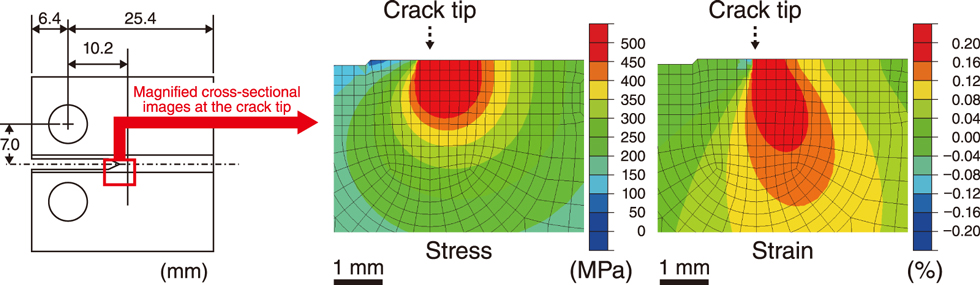
Fig.2-9 Configuration of a CT specimen and contour figures of stress and strain near a crack tip in a 7-kN loaded CT specimen (K = 30 MPa(m)1/2) immersed in a simulated BWR coolant condition
The FEA results show a lower half of the crack tip in the specimen.
Go back by your web browser, or click the right button.« Close