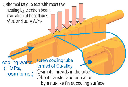
In a fusion machine, a divertor is the only in-vessel component in contact with plasma. In this service, a divertor will receive a steady-state high heat flux in excess of 20 MW/m2, which exceeds heat loads applied to general engineered components. We have proposed applying a screw tube heat exchanger using pressurized water flow for divertor cooling. In the screw tube design, the cooling surface has threads like a nut, which enhance heat transfer by promoting continuous mixing of flowing water near the heat-transfer surface. Experimental results show a screw tube heat exchanger has higher heat removal capability than does a swirl tube with an inserted twisted tape, which is the type adopted for the ITER divertor.
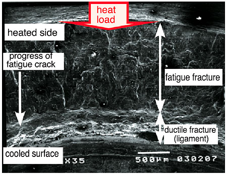
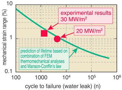
During service, the screw tube heat exchanger is exposed to cyclic heat loads; however, it has been noted that the screw thread roots potentially act as crack initiators. Therefore, the thermomechanical features of the screw tube have been studied experimentally and numerically (Fig. 2-12). In the experiments, repetitive heat loads of 20 and 30 MW/m2 were applied to the screw tube mock-up formed from a copper (Cu)-alloy, CuCrZr, (a candidate material of the ITER divertor cooling tube). The experiments continued until a water leak due to thermal fatigue occurred in the cooling channel. Using finite element analyses, the thermomechanical behavior of the screw tubes under the applied experimental conditions were investigated. The screw tube fatigue lifetimes based on the mechanical strain in the tube walls were predicted. In Fig. 2-13, the fatigue lifetime prediction of the screw tube (solid line) and the experimental results (cycle number to failure or occurrence of water leak) are plotted. Both results are in good agreement. This indicates that the fatigue lifetime for a cooling channel with complex geometry like a screw tube can be predicted with the aid of numerical analyses. Fractographic observations at the water-leaked wall (Fig. 2-14) show that the fatigue crack started from the heated outer surface and propagated toward the cooled inner surface. This indicates that the screw geometry did not act as a crack initiator under the single-sided high heat load imposed on divertors.
From the results of the thermomechanical tests performed so far, the applicability of a screw tube heat exchanger for divertor cooling has been demonstrated. Further studies that include the electromagnetic effects on a cooling channel are planed to examine the suitability of the screw tube cooling technology on fusion machines.
|
 ,
,  ).
).