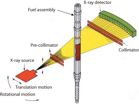
Fig.1-43 Outline of X-ray CT system
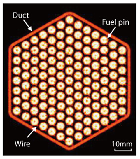
Fig.1-44 X-ray CT image of irradiated fuel assembly
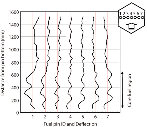
Fig.1-45 Longitudinal deformations of fuel pins
In order to develop the fuels and materials to be used for a fast breeder reactor which has economic efficiency and high reliability, it is very important to confirm the irradiation performance by a Post Irradiation Examination (PIE). Non destructive PIEs for the fuel assemblies irradiated in the "JOYO" reactor are performed in the Fuel Monitoring Facility (FMF). An X-ray Computer Tomography (X-CT) apparatus was installed in the FMF in order to observe the inner condition of an irradiated fuel assembly.
In this study, the X-CT technique developed in the medical field was established to apply to the inspection of the irradiated fuel assembly (Fig.1-43). This was the first attempt at applying this technique to PIE in the world.
In order to reduce the effect of γ-ray from an irradiated fuel assembly, a high energy X-ray was selected, and the detection period of X-rays passing through the irradiated fuel assembly is synchronized the generated pulse of high energy X-rays, using CdWO4 as the material of the scintillation detector because of its high sensitivity for high-energy photons.
As a result, a clear cross sectional CT image (Fig.1-44) of the fuel assembly irradiated to high burn up can be obtained. Analyzing this image enables measurement of the displacement of fuel pins in the assembly and the change of sodium flow area.
Fig.1-45 illustrates the longitudinal deformations of 7 fuel pins located in the center line of the fuel assembly. As shown in this figure, the deformations of fuel pins at the core fuel region are significant compared with the deformations of fuel pins at other regions. This behavior was caused by the irradiation creep of the core. Evaluation of the temperature effects on the fuel assembly will be aided using these data
<Previous: 1-16 | Next: 2 Research and Development on Geological Disposal of High-Level Radioactive Waste >

