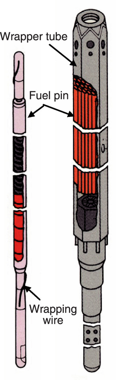
Fig.12-11 Schematic diagram of fuel pin and assembly for "JOYO"
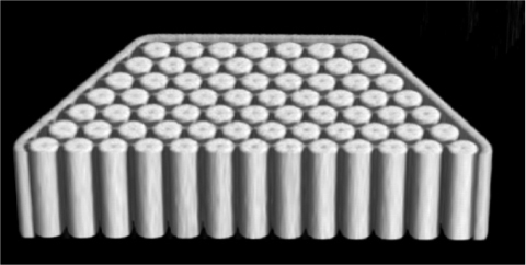
Fig.12-12 Three-dimensional X-ray CT image of the irradiated fuel assembly
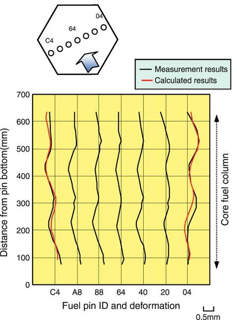
Fig.12-13 Comparison between the observed and calculated fuel pin deflection
Under irradiation, the fuel pins of a fast breeder reactor (FBR) are deflected by different amounts along the axial direction. Three factors can be envisaged that cause pin deflection: (1) bundle-duct interaction, (2) wrapping wire tension against pin, (3) thermal bowing of fuel pin. It is, however, difficult to observe fuel pin deformations in the actual assemblies because the wrapper tube prevents direct inspection (Fig.12-11). In order to observe the structural change in the interior of irradiated fuel assembly such as fuel pin deflection, a non-destructive post irradiation examination technique using X-ray computer tomography (X-ray CT) was developed (Fig.12-12).
In this study, X-ray CT images were taken on 20 cross sections along the full length of a fuel assembly which had been irradiated in "JOYO" to 78 GWd/t maximum burnup, and the deflection behavior of a fuel pin along the axial direction in the assembly was analyzed from the obtained CT images. Fig.12-13 shows the horizontal deflections of the center of 7 fuel pins in a fuel assembly along the axial direction. As shown in this figure, the displacement of all of fuel pins coincided with the wrapping wire winding pitch over the full length of fuel pins. Furthermore, the displacements of the fuel pins loaded in the outermost portions of the assembly are large, compared with the fuel pins of the central region.
The fuel pins are deflected in the axial direction by the three factors described previously. Of these factors, the contribution of bundle-duct interaction to the fuel pin deflection is negligibly small, because the neutron fluence of this assembly was low level. Thus, the fuel pin deflection induced by wrapping wire tension and thermal bowing was evaluated.
In the case of the fuel pins loaded in the outermost array, the cladding temperature rises more on the side facing inward than on the opposite outer side. This temperature difference results in a tendency for the pin to deflect outward (thermal bowing). In our calculation, it is estimated that the maximum displacement of the fuel pin loaded in the outermost array is about 0.2 mm.
Additionally, the fuel pins will undulate with the pressure imparted by wrapping wire tension, with the undulations coinciding with the pitch of the wrapping wire. In the calculation, the fuel pin displacement induced by the wrapping wire tension is about 0.16 mm.
Overall deformation was obtained as the sum of these two deformations. The calculated deformation along the axial direction of two fuel pins loaded in the outermost array in the assembly are shown in Fig.12-13. The red lines on the graph correspond to calculated results. The results agree with each other.
The composition of X-ray CT images of the successive cross sections taken at a short interval made it possible to determine the deformation of fuel pins along the axial direction. The results obtained for the fuel assembly irradiated in "JOYO" showed good agreement with predictions. This knowledge makes it possible to predict the deflection of fuel pins loaded in the assembly under irradiation.

