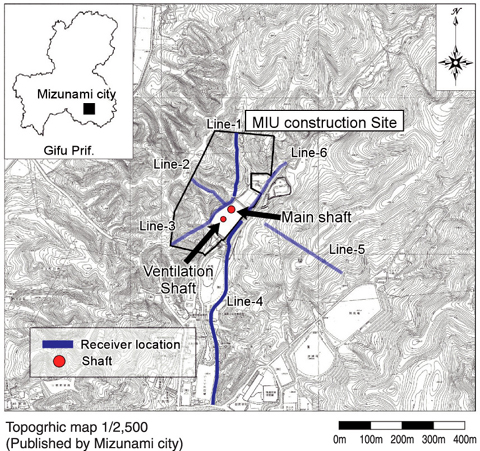
Fig.2-14 Survey location
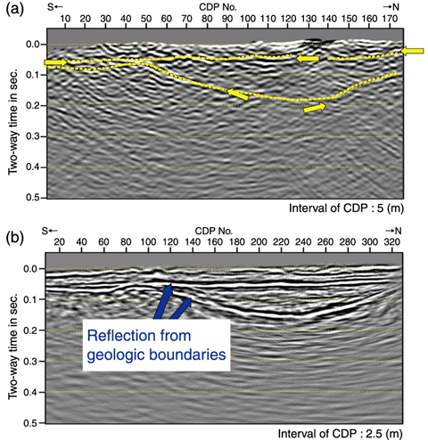
Fig.2-15 Comparison of the reflection seismic profile made from excavation vibration records (a) and conventional shot reflection seismic profile (b)
It's very important for the geological modeling of the disposal sites of HLW to understand the three-dimensional structure of geological elements (e.g. geological boundary and fault) that influence the groundwater flow. Generally, remote sensing, airborne geophysical surveys, surface geophysical surveys, geological mapping, borehole investigation etc. are applied to obtain the geological information from the surface. In this paper, the underground imaging technique using the blasting vibration during shaft excavation is introduced, as one more surface geophysical method.
We are constructing the Mizunami Underground Research Laboratory (MIU) in Mizunami city, Japan. The MIU is composed of two shafts to depth of 1,000 m (Main shaft: φ 6.5 m, Ventilation shaft: φ 4.5 m) and drifts every 100 m. In this study, the blasting vibration, which is generated by the shaft excavations, was used as a seismic source, and the imaging of subsurface structure was attempted. This method is similar to a conventional reflection seismic survey. Geophones were arranged in regular array on the surface as shown in Fig.2-14. However, this method doesn t need seismic source shots at regular intervals like a conventional reflection seismic survey. This method can synthesize the same number of shot records as the receivers, with only one seismic source event. The reflection response can be obtained by the cross-correlation of the transmission responses on the surface.
Fig.2-15 shows a reflection seismic profile made from synthesized shot records taken in Line-1 and Line-4 (a) and a conventional reflection seismic profile (b). The reflectors in the reflection seismic profile made from synthesized shot records are confirmed.
A clearer subsurface structure image can be obtained by adding more vibrations produced during the MIU construction.
An advantage of this method is that one can simulate a number of extra shot records proportional to the number of receivers. Therefore, it can be easy to investigate in three-dimensions from the surface.

