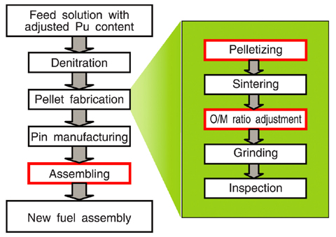
Fig.1-31 Process flow of simplified pelletizing fuel fabrication
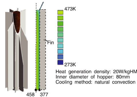
Fig.1-32 Powder supply hopper and temperature distribution
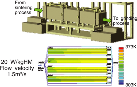
Fig.1-33 O/M ratio adjustment furnace and temperature distribution
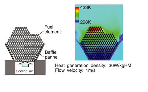
Fig.1-34 Concept of fuel assembling equipment and temperature distribution
TRU fuel is being considered as a future FBR fuel because it can decrease the environmental burden by closing in minor actinides (MA) such as americium and curium in the nuclear fuel cycle. The TRU fuel generates high heat on the order of tens of W/kgHM (kgHM means weight of heavy metal element in the fuel material) by the decay of the contained MA. Heat generation by the fuel causes oxidation of MOX powder and pellets, oxidation of the cladding tube, and mechanical interference between the cladding tube and wrapper tube. Therefore, it is necessary to cool the fuel during the fuel fabrication process. In the fuel assembling process, the powder supply hopper in pelletizing process, the pellet unloading from the O/M (atomic ratio of oxygen and the metal in the oxide) ratio adjustment furnace and the fuel bundle in the fuel assembling process are considered to have overheating problems.
Concepts of a heat removal system for these areas were examined, and the temperature limit for each was evaluated through heat flow calculations. Fig.1-31 shows the process flow of a simplified pelletizing method.
For the examination, provisional temperature limits were set at 358K for powder and pellet in the air, 473K for powder in inert gas, and 573K for fuel elements and the fuel assembly.
The powder supply hopper is designed to substitute the inside contents with the inert gas and has heat radiation fins were installed outside to cool the hopper naturally (Fig.1-32). The O/M adjustment furnace is designed to cool down pellets to 358K in a reduction atmosphere, and then to unload pellets while cooling them with air (Fig.1-33). The fuel assembling equipment is designed so that cooling air is blown from under the fuel element bundle (Fig.1-34).
Based on these designs, temperature distribution was evaluated with heat flow calculations (Fig.1-32, Fig.1-33 and Fig.1-34). Especially for fuel element bundle, because there are complex passages with many cladding tubes and wrapping wires, evaluation with a model of 20,000 meshes and evaluation with a detailed model of up to five million meshes were combined. Temperature distribution was calculated for various heat generation densities and cooling conditions, and the size of container and/or cooling conditions with which the maximum temperature of the fuel doesn't exceed the temperature limit were confirmed.
From these examinations and evaluations, the prospect of keeping below the temperature limit by combining natural cooling and forced cooling was confirmed for fuel with heat generation density 20W/kgHM.
<Previous: 1-10 | Next: 2 Research and Development on Geological Disposal of High-Level Radioactive Waste >

