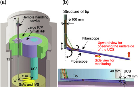
Fig.14-17 Remote handling device for observing the underside of the UCS
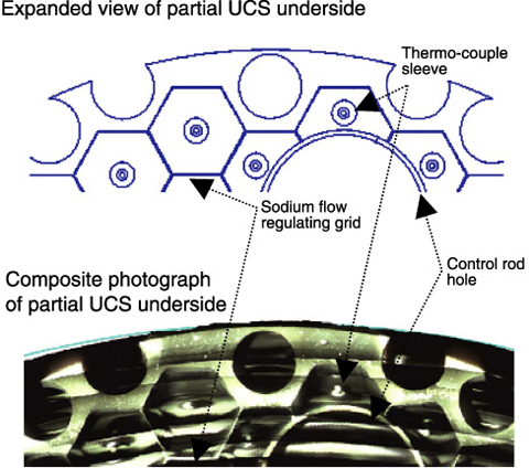
Fig.14-18 Observation results for the underside of the UCS
In-vessel observation techniques for a sodium cooled fast reactor (SFR) are important issues for confirming safety and structural integrity. Since in-vessel observation of SFRs has to be conducted under high temperatures (~200 °C) and a high radiation dose rate, the properties of the in-vessel observation equipment are required to withstand the severe conditions in the reactor. Also, because the primary sodium coolant must be contained in the reactor to remove the decay heat, it is necessary for the reactor vessel to be completely sealed during the observation. Therefore, in-vessel observation equipment is also required to pass through the fixed hole built on the rotating plug to access observation areas.
In order to verify in-vessel observation techniques in a SFR, in-vessel observations with a radiation-resistant fiberscope were carried out in the experimental fast reactor“JOYO” (sodium-cooled fast reactor; thermal power: 140 MW), with an obstacle on the in-vessel storage rack as the opportunity.
The objective was observation of the underside of the upper core structure (UCS).
As shown in Fig.14-17, a remote handling device which has a tip that can be bent into an L-shape has been developed for observation of the underside of the UCS. This device has two fiberscopes: one for an upward view and the other for a side view. The tip of the device was inserted into the 70 mm gap between the top of the S/As and the bottom of the UCS. The sodium level was kept at 50 mm below the top of the S/As during these observations. Before the observations, a full scale mock-up test was conducted to confirm the performance of the remote handling device.
As a result of these observations, the 8.0 mm thick sodium flow regulating grid on the underside of the UCS could be confirmed by radiation-resistant fiberscope while adjusting the lighting and the depth of focus as shown in Fig.14-18. These results provided valuable insights for further improvements in, and verifications of, SFR in-vessel observation techniques.

