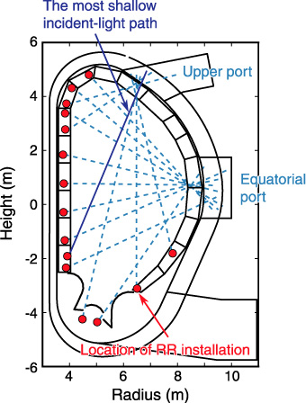
Fig.3-10 Cross section of ITER vacuum vessel and incident-light paths in ITER poloidal polarimeter
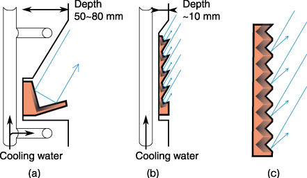
Fig.3-11 (a) Installation of RR (b) Installation of TERRA (c) Conventional RR array
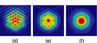
Fig.3-12 Intensity distribution of light reflected by TERRA
It is well known that information about the magnetic field structure in the plasma (or equivalently, the plasma current profile) is essential for steady-state and high-performance operation of Tokamak devices. In order to measure the magnetic field in the plasma, poloidal polarimeters have been installed in several devices. Such polarimeters will be installed in the ITER as well (Japan is in charge of the development of an ITER poloidal polarimeter). Far-infrared laser light injected in the plasma is reflected by a corner-cube retroreflector (RR) and returns to a diagnostic room. The angle of rotation of the polarization plane of the laser light provides information about the magnetic field (and electron density) in the plasma. RRs will be installed in dedicated holes at the center of the first wall panels of blanket modules. However, it seems difficult to implement inclined holes at the optimum locations owing to interference from the intricate system of cooling water pipes inside the first wall panels (Fig.3-11(a)). In particular, the RR for the viewing chord, which is shown by the blue solid line in Fig.3-10, occupies a large space. In order to install RRs at the optimum locations, we developed a terrace retroreflector array (TERRA) which is an array of small, inclined RRs. When the angle of incident light is small a conventional RR array cannot return light parallel to the incident-light path (Fig.3-11(c)). However, TERRA can return light parallel to the incident-light path because the small RRs constituting this array are inclined. Owning to the thin structure of TERRA, the installation space is reduced (Fig.3-11(b)), and thus, high cooling capability is achieved.
The light beams reflected by the small RRs interfere with each other and propagate in a particular direction. Fig.3-12 shows the intensity of the reflected light. The intensity distribution is very complicated just after the reflection (Fig.3-12(d) and (e)). When TERRA is deformed by thermal stress, the propagation direction and intensity distribution vary. We evaluated the deformation of TERRA in the ITER and found that light power returning to the diagnostic room was about 50% of the incident light power and that the polarization state was nearly unchanged.
Accordingly, we successfully developed an innovative in-vessel mirror and provided a crucial basis for the design of the ITER poloidal polarimeter.

