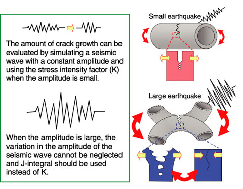
Fig.5-10 Illustrations of earthquake waves (left) and the crack growth behaviors in piping subjected to earthquakes (right)
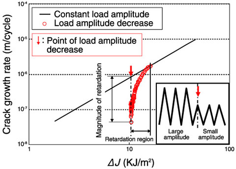
Fig.5-11 Test results for the crack growth rate when the amplitude of the applied wave was decreased (austenitic stainless steel)
The amount of crack growth must be evaluated when a crack is found in any component important for plant safety. However, an evaluation method for crack growth during seismic loading has not been explicitly stipulated in codes and standards. In recent years, Japanese nuclear power plants have experienced multiple large earthquakes, such as the Niigata-ken Chuetsu-Oki earthquake in 2007 and the Great East Japan Earthquake in 2011. For such large earthquakes that exceed the design basis seismic loading, an appropriate method is required to predict the crack growth behavior. The amount of crack growth can be evaluated using the stress intensity factor range (ΔK). However, ΔK is inappropriate for the high level of loading in the case of large earthquakes. Therefore, we have studied an evaluation method for crack growth during large earthquakes, which is shown in Fig.5-10; the method is based on the J-integral range (ΔJ), which is applicable for a high level of loading.
At first, crack growth rate tests were performed to understand the crack growth behavior under large-amplitude cyclic loading. It was confirmed from the results that ΔJ should be used instead of ΔK to evaluate the crack growth.
Next, crack growth tests were performed with cyclic loads. The load amplitude was changed stepwise, as shown in Fig.5-11. When the amplitude was increased, the crack growth rate could be predicted from the results of constant amplitude loading. In contrast, it can be seen from Fig.5-11 that the crack growth rate was retarded when the amplitude was decreased. On the basis of analytical studies, it was shown that the magnitude of the retardation can be estimated from the plastic region size in front of the crack.
Furthermore, a method to calculate ΔJ per cycle has been developed. This method calculates ΔJ for any cyclic wave pattern by considering the irregular loading history such as that in the case of earthquakes.
Considering the above results, we have proposed a crack growth evaluation method for large earthquakes; the method is a combination of methods for the evaluation of the crack growth rate on the basis of ΔJ, the estimation of the retardation effect, and the calculation of ΔJ. The proposed method is expected to be used for the prediction of crack growth during large earthquakes.

