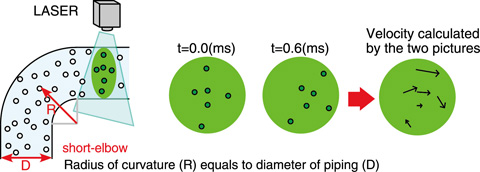
Fig.2-4 Schematic diagram of the PIV (Particle Image Velocimetry) method
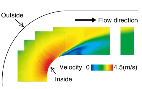
Fig.2-5 Distribution of the average velocity
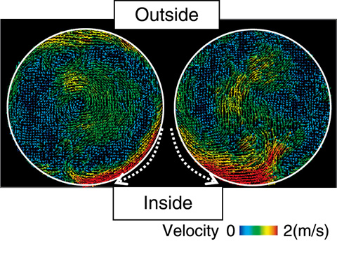
Fig.2-6 Instantaneous velocity distributions in the cross-section of the pipe at the elbow outlet
In the design of the Japan Sodium-cooled Fast Reactor (JSFR), a large diameter short elbow (D≈1.2 m) was adopted as a part of the primary hot leg pipe. The short elbow causes high turbulent flow due to changes in the flow direction over a short distance. When the frequency of the flow fluctuation is close to the characteristic vibration frequency of the piping, the piping may vibrate destructively. This phenomenon is called “Flow-Induced Vibration (FIV).” For the design of the JSFR, it was therefore necessary to understand the flow structure and flow fluctuation in the elbow in order to evaluate the structural integrity of the hot-leg piping with respect to FIV. Thus, water experiments were conducted using a 1/8-scale elbow in order to investigate the flow structure and hydrodynamic phenomena in the elbow for clarification of the FIV mechanism and to evaluate the integrity of the design.
In these experiments, the flow structure was investigated using a PIV (Particle Image Velocimetry) method. Two successive images of a fine particle tracer in the fluid were captured using a high-speed camera, and the velocity fields were measured on the basis of the movement of the tracer in the fluid calculated using the two images (Fig.2-4). The velocity field in the elbow using PIV can be seen in Fig.2-5. We succeeded in measuring the flow structure inside an elbow, including the flow separation, and quantitatively determined the frequency of the flow fluctuation. In addition, we succeeded in measuring the secondary flow in the cross-section of the pipe, which has not been measured in previous studies (Fig.2-6). At the elbow outlet, it was found that the circumferential secondary flow moved to the inside of the elbow, alternating from both lateral sides, and the velocity fluctuated intensely near the inside wall. Using these experimental results, it was possible to explain the mechanism of the flow structure and develop not only the proposed guidelines for the FIV evaluation of the hot-leg in the primary cooling system of sodium-cooled fast reactors but also the design of piping in the JSFR.

