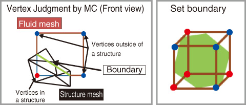
Fig.11-8 Setting of boundaries using MC
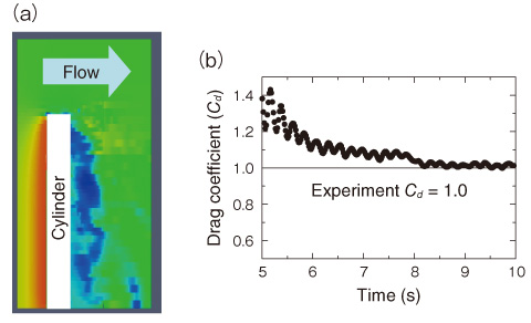
Fig.11-9 Pressure and time variations in drag coefficient
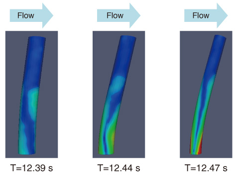
Fig.11-10 Time variations in cylinder deformation
Flow-induced vibration is a very important phenomenon in a nuclear power plant because it causes breaks in the instruments or pipes. To analyze this phenomenon, fluid structure interaction simulation technologies have received considerable attention in recent years. In a fluid structure interaction simulation, a mesh consisting of small polyhedra is generally used to describe the fluid and structure regions. To date, a method that describes accurately the shape of the boundary between the fluid mesh and the structure mesh has been used. In this method, when the structure shape is highly deformed, the mesh shape also becomes awkward. Consequently, the simulation accuracy and speed are reduced. One of the methods of overcoming this problem is the immersed boundary method. However, setting the boundary conditions in the calculation domain requires considerable time.
In this study, a new algorithm that uses Marching Cube (MC) to set the boundaries approximately was invented (Fig.11-8). The processing speed is more than 20 times faster than that of traditional methods. This makes it possible to finish a simulation that requires half a year by traditional methods within 10 days. Consequently, the method enables us to perform more practical simulations.
For verification, the method was applied to a simulation of the flow-induced vibration around a circular cylinder. Figs.11-9(a) and 11-10 show that the simulation can compute the deformation of a cylinder due to a pressure difference around it. The drag coefficient (Fig.11-9(b)) and amount of deformation of the cylinder are in good agreement with the experimental data. This study confirmed that the proposed method maintains adequate accuracy for application to practical problems.
This method enables us to perform large-scale complex simulations of flow-induced vibration with adequate accuracy within a practical timeframe. It is hoped that the method will contribute to the development of technologies to increase the safety of nuclear power plants.
<Previous: 11-3 | Next: 12 Development of Science & Technology for Nuclear Nonproliferation >

