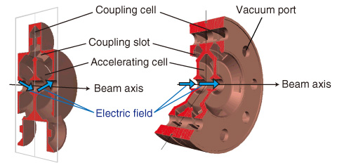
Fig.13-8 Side-coupled structure (SCS, left) vs. annular-ring coupled structure (ACS, right)
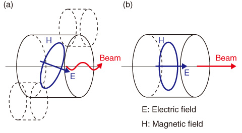
Fig.13-9 Schematic comparison of accelerating field of SCS (left) and ACS (right)
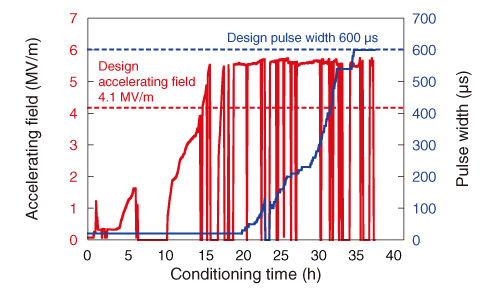
Fig.13-10 Power test result of ACS
The J-PARC linac is a 181 MeV linear accelerator that injects protons generated by an ion source to the Rapid Cycling Synchrotron (RCS) with a repetition rate of 25 Hz. The goal of J-PARC is to achieve a 1 MW output beam power, which would be the largest worldwide, for the Materials and Life Science Experimental Facility.
Minimizing the beam loss to maintain machine activation within the permissible level is one of the most important issues for high-intensity proton linacs, including J-PARC. The space-charge effect arising from Coulomb repulsive forces among beam particles is one of the causes of beam loss in the RCS. This effect can be reduced by increasing the injection energy of the proton beam. Thus, an injection energy upgrade of the J-PARC linac from 181 to 400 MeV is planned. An annular-ring coupled structure (ACS) has been developed for this energy upgrade (Fig.13-8).
Because of the axially asymmetric structure of the ACS, it has a negligibly small transverse accelerating field component, which kicks the proton beam perpendicularly to the beam axis and is smaller in the ACS than in the side-coupled structure (SCS) (Fig.13-9). Proton linacs use several types of accelerating structure depending on the beam energy. The ACS realizes energy efficiency and stability comparable to those of the SCS, which has been used for the same energy region as the ACS. Consequently, the injection energy can be increased while reducing the beam loss of the linac.
A prototype module for the ACS for the J-PARC linac was designed and fabricated, and it was successfully conditioned up to the designed accelerating field (Fig.13-10). This is considered to be a big step toward the energy upgrade of the linac and realization of 1 MW beam operation. A total of 25 ACS modules have been completed to date and are being prepared for installation. In FY2013, we will finish the installation and start the world’s first beam acceleration by an ACS.

