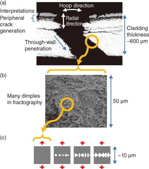
Fig.2-3 Failure of long-term used fuel cladding and modelling
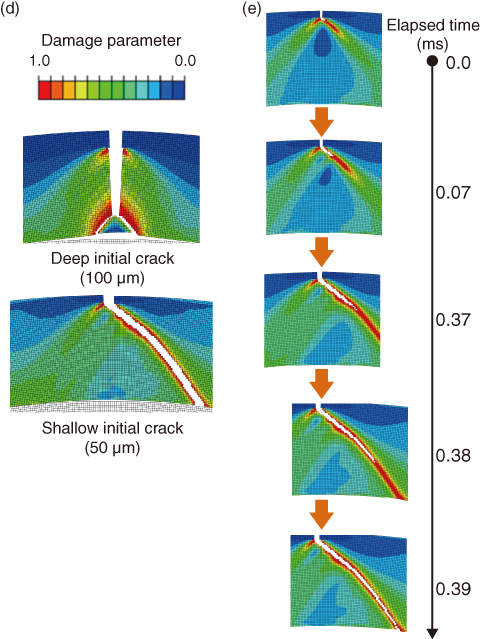
Fig.2-4 Simulation results
Reactivity initiated accident (RIA), a power excursion caused by control rod ejection, is one of the accidents assumed to confirm safety design of nuclear reactors. In Japan, the failure limit of long-term used fuels for RIA is postulated to be lower than that of fresh fuels, based on RIA-simulated tests conducted at the Nuclear Safety Research Reactor. Although the lower failure limit was considered to be caused by through-wall penetration of cracks which were generated in the cladding peripheral region with hydrogen absorbed and accumulated during reactor operation (Fig.2-3(a)), directly observing a phenomenon as rapid as fuel failure inside the reactor is not possible. Thus, the anticipated mechanism was not confirmed and the detailed processes remain unknown.
To overcome this difficulty, we developed a numerical model of fuel cladding to simulate a RIA. The cladding was modeled as an assembly of elements (Fig.2-3(c)), each about 10 μm in size. This element was designed to break upon finite deformation, as determined independently of the RIA tests. We then simulated the failure of the virtual cladding under RIA conditions, which is quite a new approach in this field, realized on the basis of accumulated test data and simulation techniques.
The simulation well reproduced the observations: fractures characterized by a predominant ductile shear in the shallow-crack case and straight-crack propagation in the deep-crack case (Fig.2-4(d)), and penetration through the wall that occurs in a very short time (<1 ms) (Fig.2-4(e)). This result strongly supports the aforementioned hypothesis and reveals that predominant ductile shear (Fig.2-3(a)) occurs when a softened region extends along the strain field around the crack tip and collapses simultaneously at a certain deformation. A sensitivity analysis using the model provides information on the influence of the loading state and temperature distribution inside the cladding on the failure limit, which supports the ongoing development of methods for safety evaluation that can accurately predict the failure limit of long-term used fuels.

