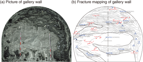
Fig.8-17 Example of fractures induced by gallery excavation
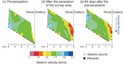
Fig.8-18 Results of seismic tomography survey
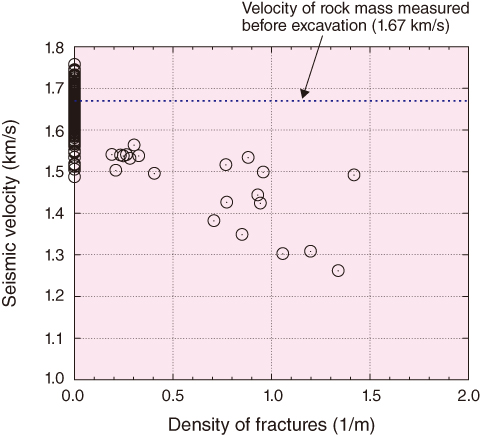
Fig.8-19 Relationship between seismic velocity and density of fracture
In the construction of a deep underground gallery, fractures are induced around the gallery wall because of stress redistribution in response to excavation, as shown in Fig.8-17. In addition, because of these fractures, the hydraulic conductivity of the rock mass increases. Such a zone is called an excavation damaged zone (EDZ). To dispose of high-level radioactive waste, evaluation of an EDZ is important for safety assessment.
The Horonobe Underground Research Laboratory is conducting a seismic tomography survey at the depth of each gallery (140 m, 250 m, and 350 m) to investigate the extent of an EDZ. Fig.8-18 shows how seismic velocity changes in response to excavation. These results were obtained from a seismic tomography survey performed in the 250 m gallery. From the results shown in Fig.8-18(c), the seismic velocity of the pre-excavation rock mass ranges from 1.6 to 1.8 km/s. From the results shown in Figs.8-18(d) and (e), the layer in which the seismic velocity decreased remarkably (<1.4 km/s) extended approximately 1.0 m in the gallery wall. To investigate the mechanism producing the variations in seismic velocity, we obtained the number of fractures intersected by the ray path of a seismic wave based on the result of the fracture mapping of the gallery wall. Next, the fracture density for each ray path was calculated by dividing the number of fractures by the length of each ray path. Fig.8-19 shows the relationship between seismic velocity and fracture density. The figure shows that seismic velocity decreases almost linearly as fracture density increases. Thus, we expect that fracture density around the gallery wall could be estimated from the seismic velocity around the gallery wall. Furthermore, hydraulic tests reveal that enhanced hydraulic conductivity extends approximately 1.2 m into the gallery wall. Consequently, the EDZ in the 250 m gallery is estimated to extend approximately 1.2 m in the gallery wall. In the near future, we will construct a conceptual model of an EDZ based on the results of in situ tests and observations made in the 350 m gallery and in vertical shafts.

