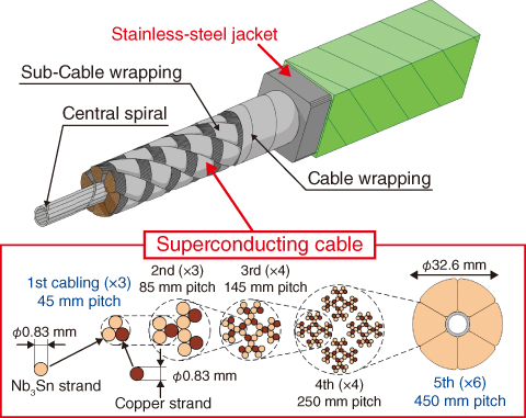
Fig.9-4 Schematics of the ITER CS conductor
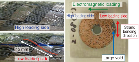
Fig.9-5 Deformation of strands in the cable after testing
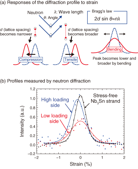
Fig.9-6 Internal strain evaluated by neutron diffraction
The central solenoid (CS) conductor for ITER, shown in Fig.9-4, is operated at 45 kA and 13 T. The conductor is required to withstand a 60000 cyclic electromagnetic loading of 50 t/m. Short sample tests found that the superconducting performance gradually degraded during these cycles. A clarification of this degradation mechanism is needed.
The performance of the Nb3Sn strands in the CS conductor is sensitive to strain. Thus, transverse electromagnetic loading has been considered a major cause of the degradation of conductors. Namely, the electromagnetic loading bends the strand at a short pitch (around 5 mm) through contact with adjacent strands in the high loading side (HLS). However, observation of the cable showed that the deflection of strands on the low loading side (LLS) was larger than that on the HLS, as shown in Fig.9-5.
The mechanism behind the strain was reconsidered. Since the fixture of the strand in the cable is relaxed by a large void, the buckling of the strand occurs due to the axial compressive force caused by different amounts of thermal contraction between the cable and the jacket.
The visual observation showed a bending strain of around 0.6% in the LLS. Since the bending strain in the HLS could not be evaluated by visual observation, a quantitative method was needed to evaluate it. Hence, a neutron diffraction measurement using the engineering materials diffractometer in the Japan Proton Accelerator Research Complex (J-PARC) was conducted to evaluate the bending strain. The average bending strains evaluated from the variation of the profile (Fig.9-6) were 0.32% in the HLS and 0.63% in the LLS. Consequently, bending with short pitch in the HLS was not dominant. The bending strains in the LLS that were evaluated by visual inspection and neutron diffraction were in agreement.
The strands’ deformation can be prevented by the optimization of cabling, since the strand withstands buckling by shortening the bending pitch. An optimized CS conductor could satisfy the requirement for 60000 operation cycles.

