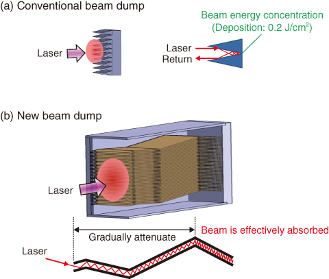
Fig.9-2 Beam dump structures
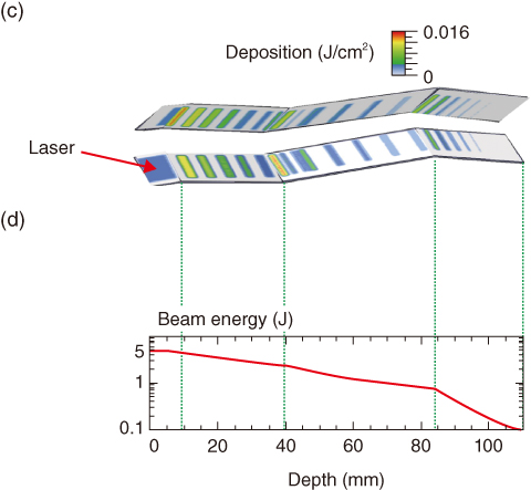
Fig.9-3 Beam energy deposition profile
When a laser beam is injected into plasma, a very small fraction of the light is scattered by electrons in the plasma. This phenomenon is called Thomson scattering. The electron temperature and density of the ITER plasma are measured from the spectrum and intensity of the scattered light, respectively. Since the proportion of incident photons that are scattered and detected as a signal in ITER is 10−14, it is very important to inject intense laser beams, to collect the scattered light effectively and to reduce the stray light of the laser beam in the Thomson scattering measurement, so that the electron temperature and density can be accurately measured with a high signal to noise ratio (S/N).
Laser beam dumps are designed to terminate intense laser beams and reduce the stray light of the laser beams. Since 109 laser pulses with a 5-J energy are to be injected throughout the 20 year operation of ITER, the concentrated laser energy in the valley of a conventional beam dump will cause serious damages to the surface (Fig.9-2(a)). The accuracy of the Thomson scattering measurement significantly degrades if the laser beam dump is damaged, since the stray light from the damaged surface of the beam dump increases. A key concept of the new beam dump is to reduce laser energy absorption per unit area on the surface and to gradually absorb the energy of the laser beam, so that the stray light will be reduced at the same time.
We have applied the idea that the absorption ratio depends on the angle of incidence and the polarization of the laser beam to the design of a new beam dump. Fig.9-2(b) shows the schematic of the newly proposed beam dump. To gradually absorb the beam energy, the laser beam is injected into the beam dump with a large angle of incidence and is polarized parallel to the beam-exposed area (S-polarization). In general, the depth should be sufficiently large to gradually absorb the beam energy. However, the allocated depth for the beam dump in ITER is up to 125 mm. The new beam dump has a number of thin molybdenum sheets with thicknesses of 0.5 mm, which are aligned parallel to each other with a separation of 1 mm. We optimized the angle and position of bending on the sheets to disperse the deposition of the beam energy (Fig.9-3).
While conventional beam dump cannot withstand more than 104 laser pulses, the new beam dump would withstand more than 109 pulses. In addition, compatibility with ITER’s thermal and electromagnetic loads was confirmed through thermo-structural analysis. We have proposed the first detailed beam dump structure in the world that complies with the severe conditions of use, installation environment, and space limitations of ITER.
<Previous: 9 Nuclear Fusion Research and Development | Next: 9-2 >

