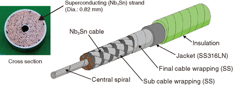
Fig.9-7 Superconductors for the ITER Toroidal Field Coils
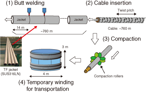
Fig.9-8 Manufacturing procedure for the superconductor
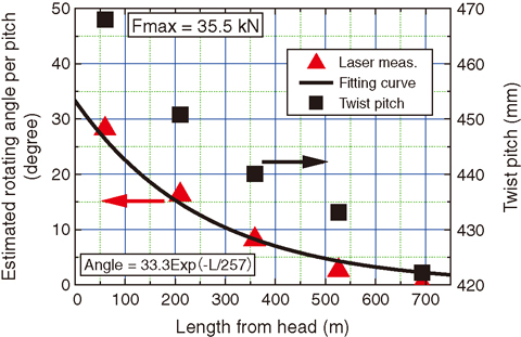
Fig.9-9 Cable twist pitch and estimated rotating angle per one pitch along the entire length
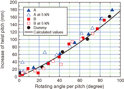
Fig.9-10 Increase of twist pitches versus rotating angle per one pitch
Around 1000 Nb3Sn strands with a diameter of 0.82 mm were cabled around the central spiral, as shown in Fig.9-7. The superconducting cables were inserted into the jacket assembled using the automatic Tungsten Inert Gas butt welding technique, as shown in Fig.9-8. The jackets were compacted to the final dimension (43.7 mm) in one step and spooled to a diameter of 4 m. It was observed that the cable pitch of the destructive sample was 474 mm, which is longer than the original pitch (430 mm) at cabling. The cables were manufactured by two suppliers and the cable twist pitches of both cables were elongated. JAEA investigated the cause of the elongation. It was confirmed that the superconducting performance of the conductors with a cable twist pitch below 493 mm is the same as that of conductors with the original twist pitch (430 mm).
The twist pitches of conductors were estimated using the Fourier analysis on the cycles of unevenness (around 0.05 mm) of the outer diameter measured continuously every 20 mm over the entire length (760 m). The twist pitch distribution is shown in Fig.9-9(■). The twist pitch monotonously decreases from head to tail.
To investigate the mechanical behavior of the cables, we performed tensile tests upon them and measured the correlation between increase of their twist pitch and the rotating angle, as shown in Fig.9-10. Calculated values in Fig.9-10(![]() ) were estimated from the twist pitches by geometrical analysis using a simple model. A good agreement between calculation and measurement is obtained. Therefore, the rotating angle during the cable insertion can be estimated using the increase of twist pitches in Fig.9-9(■) and this correlation. The estimated results are shown in Fig.9-9(▲). The total rotating angle of the cable head during the insertion can be calculated by integration of the rotating angle from head to tail. The obtained angle is 18029°, and the total number of rotations is 50 turns.
) were estimated from the twist pitches by geometrical analysis using a simple model. A good agreement between calculation and measurement is obtained. Therefore, the rotating angle during the cable insertion can be estimated using the increase of twist pitches in Fig.9-9(■) and this correlation. The estimated results are shown in Fig.9-9(▲). The total rotating angle of the cable head during the insertion can be calculated by integration of the rotating angle from head to tail. The obtained angle is 18029°, and the total number of rotations is 50 turns.
A cable rotation measurement was also successfully performed on a 760-m-long cable during the insertion using rotation sensors. The measured value was 51 turns, agreeing with the estimate.
According to these results, it can be concluded that the twist pitch was elongated during the cable insertion due to the pulling load. Since elongation is unavoidable, it is noted that this untwisting behavior of the cable should be considered during the manufacturing of conductors using this method and the manufacturing of the coil (for example terminal fabrication).

