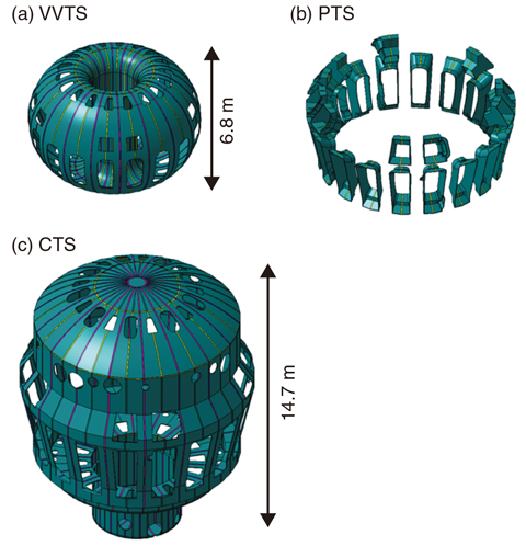
Fig.9-13 Thermal shields (TS) for JT-60SA
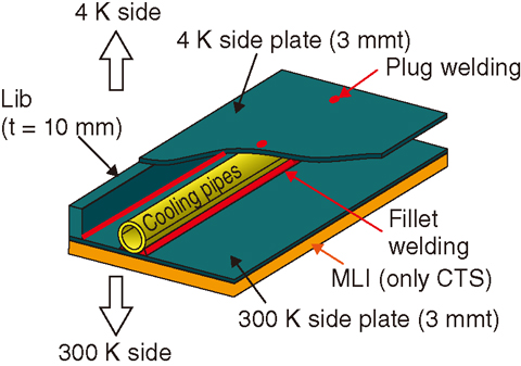
Fig.9-14 Concept of TS
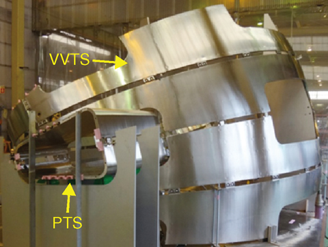
Fig.9-15 Pre-assembly of VVTS
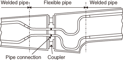
Fig.9-16 Flexible pipe for assembly
JT-60SA is a fully superconducting tokamak device for confining 100 MK plasmas in power-breakeven-equivalent conditions. The superconducting magnet system comprises 18 toroidal field (TF) coils (D-shape), a central solenoid (CS) with four modules, and six equilibrium field (EF) coils (circular shape). The cryostat provides the vacuum environment to stop convective heat transfer to the superconducting magnetic components. The thermal shield (TS) minimizes the heat loads transferred by thermal radiation and conduction from room temperature components to the superconducting magnetic components at 4 K.
The TS comprises three main parts: the vacuum vessel thermal shield (VVTS), the cryostat thermal shield (CTS), and the port thermal shield (PTS), as shown in Fig.9-13. The TS comprises two 3-mm-thick stainless steel plates reinforced by ribs and cooling tubes installed between them, as shown in Fig.9-14. The surface of the plate is polished in the same function as a mirror (emissivity: 0.15). The VVTS has to be divided electrically into 18 toroidal segments and one poloidal segment to avoid excessive eddy current heating. Cooling pipes are connected after each TS (20°) panels are assembled to the already mounted TS on the vacuum vessel of JT-60SA.
Several trials of manufacturing the VVTS are conducted to satisfy the component’s tight tolerance (±5 mm at 6.8 m in height). The VVTS, as a thin welded structure, has a large deformation during welding of the pipe and ribs. Shape correction methods of VVTS are established with the mechanical deformation by a jack after pipes and ribs are welded onto the 3 mm plate. Each connecting coupler between the panels is customized to adjust the bolt hale during the preassembly stage (Fig.9-15).
The TS panels are assembled with couplers during on-site assembly. After assembly is complete, cooling pipes are connected by butt welding. The positions of the pipe ends move slightly because the shape of the panel is deformed when the bolt of the coupler is fixed. Thus, each pipe needs flexible parts to adjust the position of the pipe ends within ±2 mm. This flexibility of pipe position is created by the bends of the pipe itself, as shown in Fig.9-16, because bellows cannot fit a space between two plates.
Some VVTSs for the JT-60SA have been manufactured (Fig.9-15) by the shape correction method and the adjustment of pipe position by a flexible pipe. VVTS will be assembled on the vacuum vessel at the Naka site.

