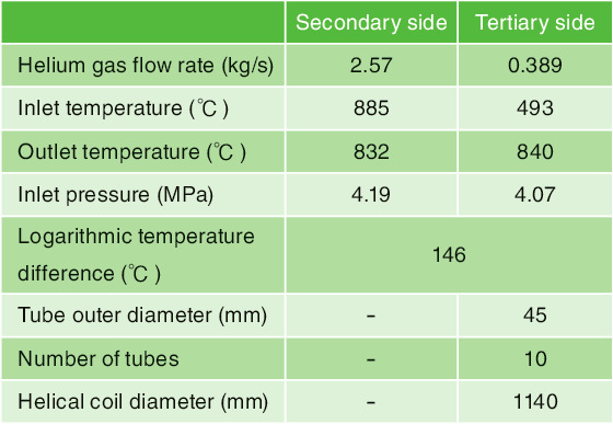
Table 6-1 Design condition of a 0.7-MW 2nd IHX assuming HTTR-GT/H2


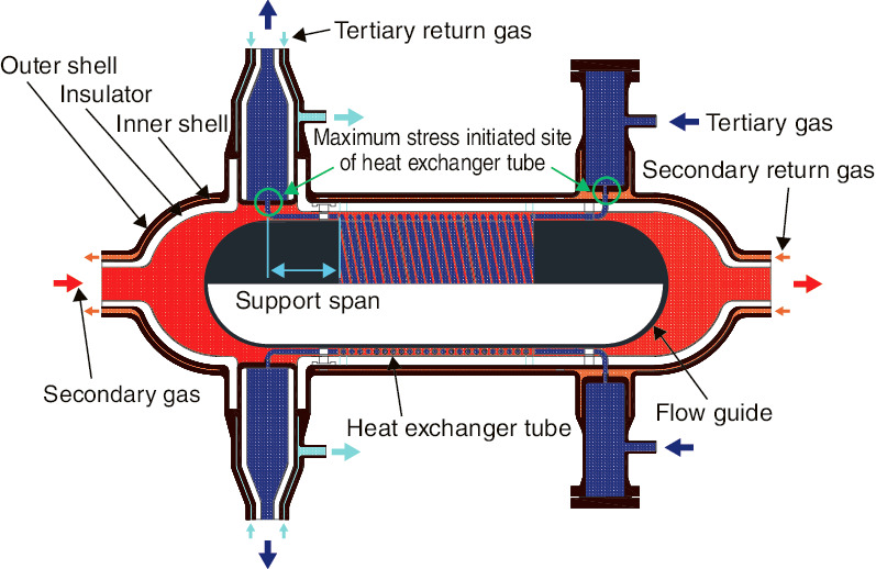
Fig.6-4 Conceptual diagram of a 0.7-MW 2nd IHX assuming HTTR-GT/H2
Toward the development of high-temperature equipment for thermal utilization of High Temperature Gas-cooled Reactors (HTGRs), an intermediate heat exchanger (IHX) and a gas turbine are installed in series to supply heat to a hydrogen-production facility. In this manner, a gas-turbine high-temperature-reactor system (GTHTR300C) capable of efficiently supplying heat to hydrogen production and power generation has been researched and developed. For demonstration purposes, a hydrogen-production system (HTTR-GT/H2) using iodine-sulfer process (IS process) with power generation by a helium-gas turbine connected to the High Temperature engineering Test Reactor (HTTR) is designed and studied. IHXs are important equipment for high-temperature-gas-furnace-heat utilization. As they are used under high-temperature environments, equipment having high-temperature creep strengths are required to ensure structural integrity, running the risk of an increased manufacturing cost. Therefore, we propose a structural concept for a horizontal-type IHX for the purpose of improving creep strength and cost and evaluate these quantities for GTHTR300C.
The exchange-heat condition of the second IHX designed for HTTR-GT/H2 (the intermediate heat exchanger between the secondary and tertiary helium) is 0.7 MW. To prevent the tertiary-system gas from entering the secondary-system side, the pressure on the secondary-system side is set 0.12-MPa higher (Table 6-1). The horizontal-type second IHX is composed of inner and outer shells, a flow guide, a heat-exchanger tube, and so on. In the case of the horizontal-type IHX, a center pipe is not needed to support the heat-exchanger tube and therefore acts only as a flow guide. Thus, it is possible to reduce the quantity of material while ensuring the same aseismic strength as a vertical-type IHX.
In the horizontal-type second IHX (Fig.6-4), secondary-system gas (![]() ) flows through the inner shell, while tertiary-system gas (
) flows through the inner shell, while tertiary-system gas (![]() ) flows through the heat-exchanger tube. Secondary gas (
) flows through the heat-exchanger tube. Secondary gas (![]() ) then returns from the helium-gas turbine flowing between the outer and inner shells, while tertiary gas (
) then returns from the helium-gas turbine flowing between the outer and inner shells, while tertiary gas (![]() ) returns from the hydrogen-production facility. Inside the inner shell, heat exchange occurs between the secondary- and tertiary-system gases, and the return gas of decreased temperature flows into the space between the outer and inner shells. Thus, the cooling effect on the outer shell side can be improved, and the thermal stress of the whole device can be reduced.
) returns from the hydrogen-production facility. Inside the inner shell, heat exchange occurs between the secondary- and tertiary-system gases, and the return gas of decreased temperature flows into the space between the outer and inner shells. Thus, the cooling effect on the outer shell side can be improved, and the thermal stress of the whole device can be reduced.
Stress calculation was performed using the general-purpose finite-element-method-based structural-analysis program ABAQUS. In addition, except at the center pipe, in the creep-life evaluation of the horizontal second IHX with reduced support stress of the heat-exchanger tube, the support span of the heat-exchanger tube necessary to withstand creep rupture of the material was shortened from 1.4 m for the vertical-type to 0.9 m. Thus, the maximum initiated stress in the heat-exchanger tube was 4.3 MPa in the vertical-type, but 1.9 MPa in the horizontal-type. Finally, a value that satisfies the allowable stress (2.6 MPa) corresponding to the cumulative-creep-damage coefficient corresponding to continuous operation for 40 years has been achieved, as compared with a designated life of 20 years for the vertical-type. For lifespan evaluation, it is thought to be necessary to verify the effectiveness of the design by acquiring creep data over a long period.
Based on the above evaluation, physical-quantity assessment of the horizontal-type IHX with an exchange heat of 170 MW at GTHTR300C was performed. Compared with the vertical-type, the weight of the material was found to be drastically reduced, and material-cost estimates are reduced by 30%.
Based on these results, the horizontal second IHX will be studied in detail in the future.