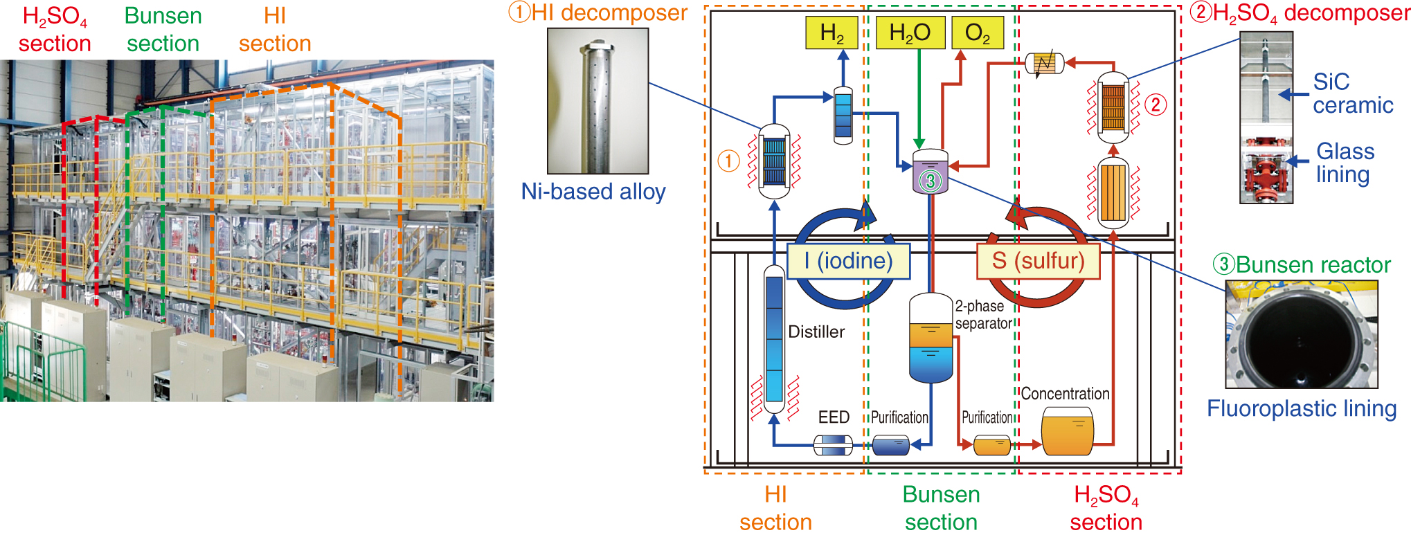
Fig.6-10 Continuous-H2-production test facility
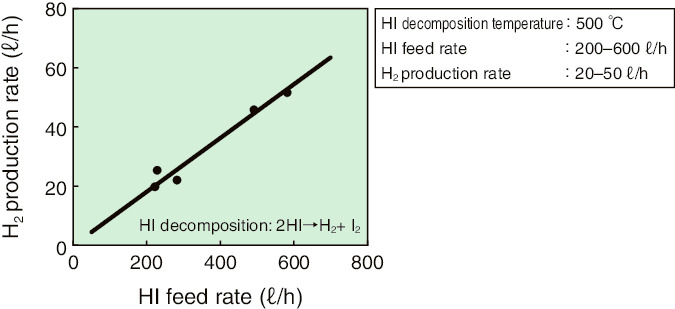
Fig.6-11 Effect of HI feed upon H2 production in a HI decomposer
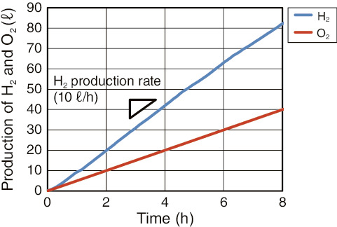
Fig.6-12 Total H2 and O2 production in a process demonstration
We have performed R&D on thermochemical hydrogen (H2)-production using iodine-sulfur (IS) process as an application of High Temperature Gas-cooled Reactor (HTGR) heat. The IS process consists of Bunsen reaction to produce hydrogen iodide (HI) and sulfuric acid (H2SO4), HI decomposition to produce H2, and H2SO4 decomposition to produce oxygen (O2). Overall, H2O is decomposed into H2 and O2. The IS process is expected to offer CO2-free H2 production because carbon is neither in the material nor in the energy source.
We succeeded in conducting a one-week continuous H2 production using a lab-scale facility in FY2004. Components in the facility was made of glass. Corrosion- and heat-resistant components of industrial materials are required for commercialization because large-scale structures cannot be made of glass.
We constructed a test facility in FY2013 by applying corrosion- and heat-resistant materials to the whole process (left in Fig.6-10). Reactors were developed and integrated into each section (right in Fig.6-10). The designed H2-production rate was 100 ℓ/h. The functionality of individual sections was verified in FY2015. Process-rate control in reactors, such as control of H2 production by HI feeding (Fig.6-11), and phase separation (such as HI distillation) were verified. Then, a demonstration was performed by coupling the 3 sections. An 8-h continuous H2 production at 10 ℓ/h was achieved in February 2016 (Fig.6-12). By checking the facilities after operations and performing operational-data analysis, we found that clogging prevention and Bunsen-solution-composition control were important for longer-term operation.
We plan to improve the facility based on these findings for longer-term operations to verify the technology and integrity of the facility.

