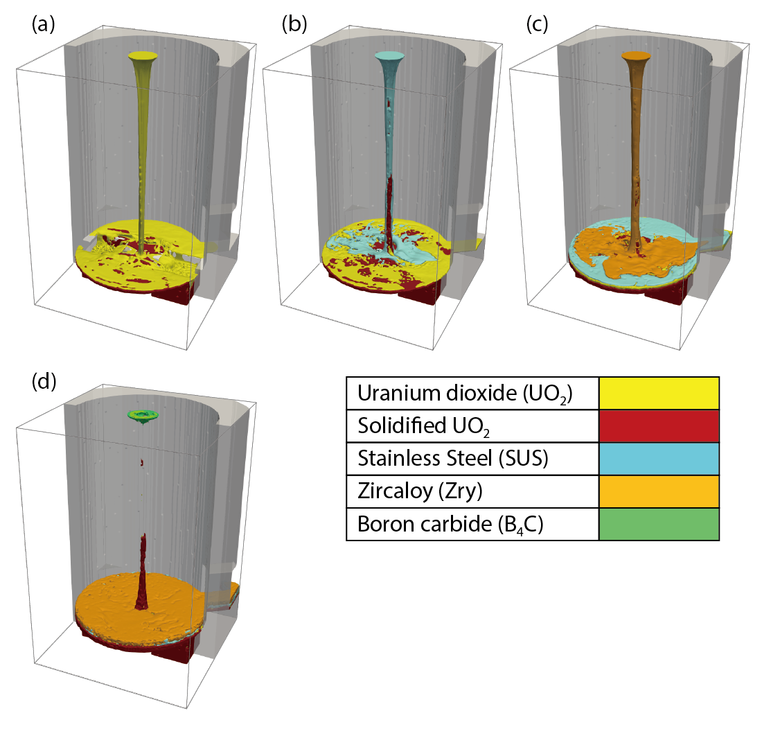
Fig.1-2 Melt-accumulation behavior (numerical result)
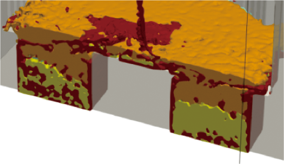
Fig.1-3 Interior distribution of accumulated debris (numerical result)
During severe accidents (SAs), fuel debris (a mixture of fuel and the other materials) is generated by melting of reactor cores and is relocated to the lower part of reactors. Information concerning fuel debris, including its distribution, composition, and re-criticality, is required for its removal. Therefore, obtaining this information is important for decommissioning of the TEPCO’s Fukushima Daiichi NPS (1F). However, melting and relocation of fuel debris are complicated phenomena, making this information quite difficult to obtain. Numerical simulations are effective tools, but conventional SA-analysis codes are of little use because they include various assumptions about phenomena and simplify the shapes of reactor-core structures to shorten the computational time.
Therefore, the fuel-debris-melting and relocation process must be simulated precisely. To this end, we have developed a numerical-simulation code for melting and relocation behavior called JUPITER, based upon a mechanistic methodology. JUPITER can simulate melting and relocation without assumptions or simplification using basic equations governing the thermal-hydraulic behavior of the fluids.
We numerically simulated melt-relocation behavior to the lower part of the primary containment vessel (pedestal) using JUPITER. In this simulation, we decided the largest-density material, molten UO2, should be poured first, followed by the lower-density materials SUS, Zry, and B4C. As shown in Fig.1-2(a), UO2 spreads over the pedestal and is accumulated in two cavities (sump pits) with solidification. Then, fuels and other materials mix in a complicated fashion (Fig.1-2(b)–(d)). Fig.1-3 shows a cross-sectional view of the pedestal along its center to illustrate the accumulation state inside the sump pits. As shown in Fig.1-3, the melt near wall of the pedestal is solidified by heat transfer to the wall. The heavier material, UO2, is located at the bottom and the lighter material, Zry, is located at the upper layer. This distribution is given by mechanistic estimation for melt relocation and solidification based upon the physical governing equations.
In addition, we try to evaluate the re-criticality of fuel debris in the pedestal using the continuous-energy-neutron-transport Monte Carlo code MVP. The required fuel-debris distribution for re-criticality analysis is evaluated using the above-mentioned fuel-debris-relocation simulation of JUPITER. In a normal re-criticality analysis, it is assumed that the fuel debris is uniformly mixed. Here, with the distribution given by JUPITER, re-criticality can be calculated using a more realistic condition. If water exists in fuel debris, re-criticality occurs readily in theory. In this simulation, we calculated re-criticality with and without water in the fuel debris. It is found that re-criticality does not occur except where an unrealistic amount of water exists in the fuel debris.
In the near future, we will validate the applicability of JUPITER to the relocation and accumulation of fuel debris by comparing simulation results with experimental ones and perform debris-accumulation simulation under several parameters. In addition, we will contribute to the decommissioning of 1F by evaluating the characteristics and re-criticality of fuel debris.
<Previous: 1 Research and Development Related to the Accident at the TEPCO’s Fukushima Daiichi NPS | Next: 1-2>

