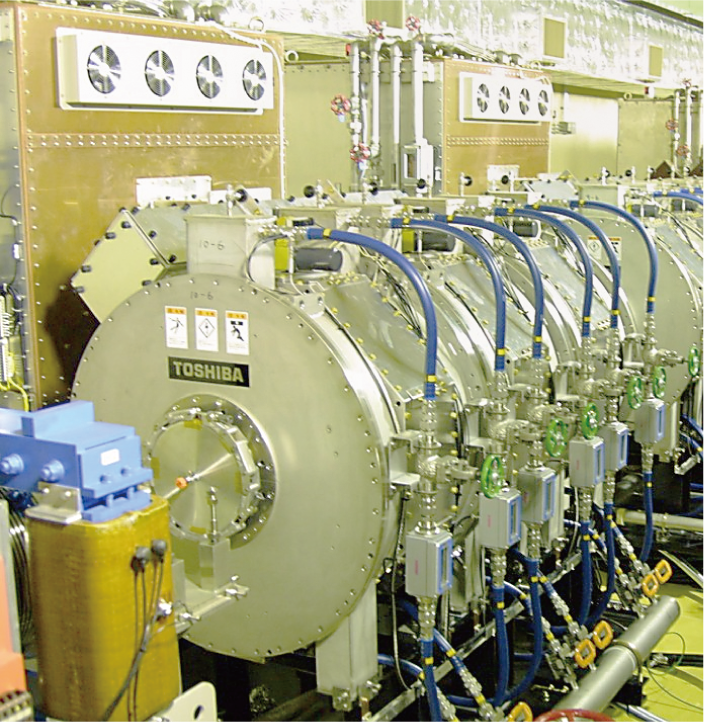
Fig.5-3 RF Cavity for J-PARC 3-GeV Synchrotron
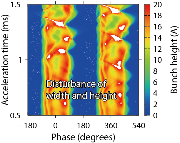
Fig.5-4 Observation of beam instability by a beam monitor
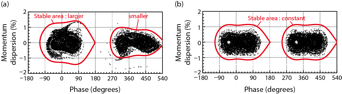
Fig.5-5 Observation of beam instability by a beam monitor
J-PARC 3-GeV rapid cycling synchrotron (RCS) accelerates high-intensity protons with a repetition rate of 25 Hz. The proton beam is accelerated by an RF voltage generated at an acceleration cavity. We have developed a magnetic-alloy (MA)-loaded cavity (Fig.5-3) instead of a Ferrite one because the field gradient must be more than twice as high as the conventional one. Furthermore, we have realized multi-harmonic RF-voltage generation in a single cavity because of the broadband characteristics of the MA, and this is the first trial for the high-intensity proton synchrotron.
However, beam instability is observed with a beam loss when the beam power is close to 1 MW, which is the design value of the RCS. Fig.5-4 shows the mountain plot of the beam monitor. The RCS accelerates two bunches, and it can be seen that the width and height of these bunches oscillate in alternation. Analysis of the beam measurement suggests that the growth time of the instability is less than one tenth of that calculated by the well-known instability theory.
We think that this unknown instability may be caused by the cavity, which has broadband characteristics. The high-intensity beam generates a “wake voltage“ at the cavity. The voltage disturbs the original acceleration voltage and causes beam loss. Although the compensation system for the wake voltage already has been prepared, it is believed that cancelling the main harmonics of the wake voltage will be enough for stable acceleration. However, the particle-tracking simulation suggests that the harmonics that were considered to be negligible in fact grow rapidly.
Fig.5-5 shows the simulation results. The protons are shown as dots and the stable acceleration area is shown as a red line. The upper graph indicates the case of instability. The stable area becomes larger and smaller in alternation and some protons are spilled out. The lower graph indicates the stable case, and the area is unchanged. We have confirmed that the broadband characteristics of the cavity cause this newly observed instability with the minor harmonics.
We have prepared a compensation system for the minor harmonics, and finally, we have achieved 1-MW beam acceleration.
<Previous: 5 Applied Neutron and Synchrotron-Radiation Research and Development | Next: 5-2>

