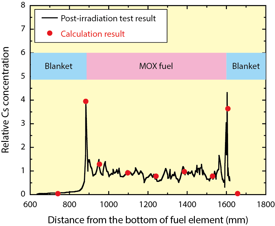
Fig.7-7 Axial distribution of the Cs concentration in a fuel element
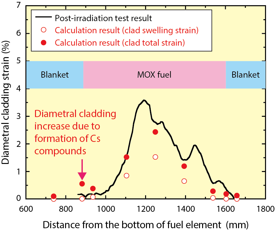
Fig.7-8 Axial distribution of the diametral cladding strain of a fuel element
In mixed-oxide (MOX)-fuel elements irradiated in fast reactors, as fuel burnup proceeds, a Fission Products (FPs), cesium (Cs), migrates to the lower-temperature regions of the fuel elements and may interact with other FPs to form chemical compounds, thereby affecting the fuel-pellet temperature and dimensional stability of the cladding. We have developed a model for analyzing Cs behaviors and incorporated it into the calculation code CEDAR, which predicts changes in the temperatures and dimensions of a fuel element. This allowed for the Cs behaviors and their impact upon the integrity of the fuel element under irradiation to be predicted.
Thermal diffusion and evaporation–condensation processes are the base of the analysis model of Cs behaviors, the idea of which was inspired by the past relevant research results. The radial and axial Cs migrations in the fuel element were calculated by applying the temperature distributions of CEDAR to these processes. Fig.7-7 shows the axial distribution of the Cs concentration in the fuel element irradiated to high burnup in the prototype fast reactor Phenix in France. The calculation of CEDAR including the Cs-behavior model showed that Cs accumulates at the upper and lower ends of the MOX-fuel column as a result of its migration in the fuel element during irradiation, thereby reproducing the actual results of locally increased Cs concentrations.
We developed a model for predicting the formation of various Cs compounds based on the calculations of chemical-equilibrium reactions between Cs and oxygen (O), uranium (U) and other FPs such as molybdenum (Mo). This model also uses temperatures and the amount of oxygen in the fuel pellets calculated by CEDAR.
The analysis of the high-burnup-fuel element showed that Cs compounds were accounted for by the Cs–Mo–O and Cs–U–O systems. The Cs–Mo–O compound is known to accumulate as a medium in the gap between the fuel pellet and the cladding, thereby decreasing the fuel-pellet temperature; it was predicted to be formed in the gap over the entire MOX-fuel-column region, which was consistent with the actual distribution of this compound. The Cs–U–O compounds are known to be formed at the parts where Cs is concentrated and, because of their lower density, may cause contact between the pellets and the cladding. In the analysis, Cs–U–O compounds accumulated at the lower end of the MOX-fuel column caused contact between blanket pellets and cladding, yet the effect of the contact pressure upon the cladding diameter was sufficiently small. As shown in Fig.7-8, the calculation by the code adequately reproduced the measured cladding-diametral strain.

