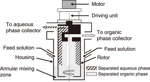
Fig.8-32 Schematic of a typical centrifugal contactor
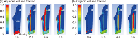
Fig.8-33 Time dependency of (a) aqueous and (b) organic volume fractions in a centrifugal contactor with a rotor diameter of 28 mm
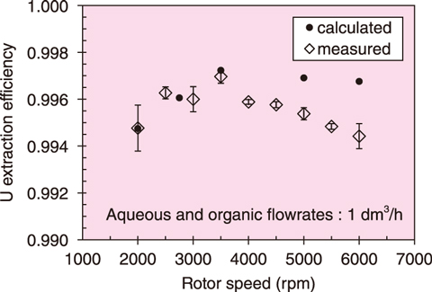
Fig.8-34 Variation of uranium extraction efficiency with rotor speed
During the reprocessing of spent nuclear fuel, several extractors are used to extract uranium (U) and plutonium (Pu) from the nitric acid dissolver solution into the organic solvent. Among various extractors, centrifugal contactors (Fig.8-32), which mix and separate the aqueous and organic phases by high-speed rotor rotation, have some attractive advantages, such as a high throughput and superior phase separation performance. The flow and dispersion behaviors of the aqueous and organic phases in this contactor are closely related to its extraction performance. As such, a numerical analysis was developed to predict the effect of operating conditions on these behaviors and U extraction. This developed model can calculate the time dependency of aqueous and organic flow and dispersion in a centrifugal contactor, as well as the change of U concentration in each phase.
The resulting time dependencies of the aqueous (a) and organic (b) volume fractions in a centrifugal contactor are shown in Fig.8-33. Each phase flowed down from the inlet and was mixed in the annular mixing zone by the rotating rotor. The dispersion entering the rotor was quickly separated by centrifugal force into the outer, heavier, aqueous phase and the inner, lighter, organic phase.
Varying the operating conditions indicated that higher rotor speed and lower flowrate divided vertically the zone with a high liquid volume fraction in the annular mixing zone into two regions, which decreased the mixing time. The liquid flow moving toward the center of the housing bottom was obtained in any conditions. Additionally, the droplet size of the dispersed phase in the annular mixing zone decreased with increasing rotor speed and decreasing flowrate. Overall, these results were in good agreement with experimental results, thus confirming the effectiveness of the designed model.
Prior U-extraction experiments using a centrifugal contactor obtained a maximum extraction performance at an appropriate rotor speed. As shown in Fig.8-34, the simulation results also showed the same tendency.
Future work will aim to apply the designed simulation to investigate the effect of the contactor structure and improve the performance of the centrifugal contactor.
This study was conducted in collaboration with YOKOHAMA National University, “Study on flow and dispersion characteristics in extractors” (2013-2017).
<Previous: 8-12 | Next: 9 Computational Science and E-Systems Research>

