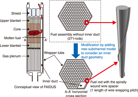
Fig.7-8 Fuel assembly with inner duct structure (FAIDUS) schematic
Table 7-1 Major specifications and boundary conditions of fuel assembly
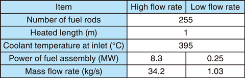
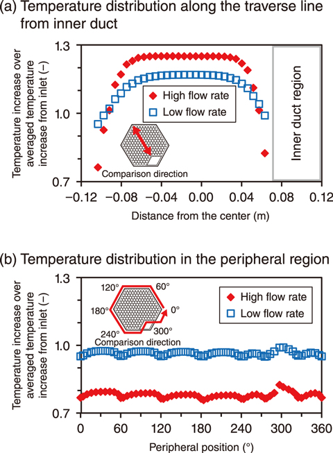
Fig.7-9 Numerical results of thermal hydraulics in FAIDUS at the top of the heated section
In the design study of a SFR, the use of a specific fuel assembly (FA) with an inner duct structure called FAIDUS, in which the inner duct of the rhombic cross-section is installed at the corner of the hexagonal wrapper tube, as shown in Fig.7-8, has been investigated to enhance safety of SFR against a core disruptive accident. In FA as well as FAIDUS, fuel rods with a spirally wound wire spacer are installed in the wrapper tube to maintain the sodium flow area. A subchannel analysis code, ASFRE, was thus developed as a FA design tool to perform parametric analyses of thermal hydraulics. In ASFRE, the control volume is a flow region (subchannel) surrounded by fuel rods or a wrapper tube. Prior research has used experimental data to validate ASFRE for FAs without an inner duct. However, it is necessary to estimate the temperature distribution with the inner duct because of the resulting asymmetrical layout of fuel rods in FAIDUS.
This work therefore aimed to further develop ASFRE by adding a new subchannel model to consider the inner duct geometry; thermal hydraulics analyses in FAIDUS were then performed at two representative flow rate conditions as listed in Table 7-1. The resulting horizontal distribution of the temperature of sodium at the top of the heated section is shown in Fig.7-9(a). At the representative low flow rate, a smaller temperature difference was indicated between the center and peripheral regions than at the representative high flow rate because the flow rate ratio in the center region increased due to the buoyancy effect in the FA. Further, the existence of the inner duct caused an asymmetric distribution at both flow rate conditions. The temperature distribution along the peripheral region on the wall of the FA is shown in Fig.7-9(b). Here, a periodic pattern at every 60° was shown, in accordance with the contact condition of the wire spacer on the wrapper tube wall, except at the corner of the inner duct, where a different contact condition was present for FAIDUS. Thus, ASFRE was deemed as valid for usage in evaluating the temperature distribution in FAIDUS.
Since experimental data of the thermal hydraulics in FAIDUS have not yet been obtained, future work will involve thermal hydraulic evaluation of ASFRE for FAs including FAIDUS through code-to-code comparisons with the detailed CFD analysis to confirm the accuracy of the evaluation results presented here.
(Norihiro Kikuchi)

