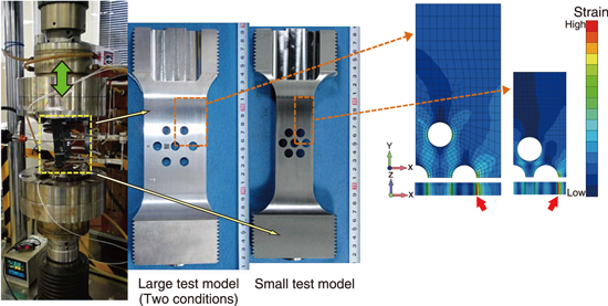
Fig.7-7 Test situation of the multi-perforated plate (Left figure)
Fig.7-8 Strain simulation by inelastic analysis (Right figure)
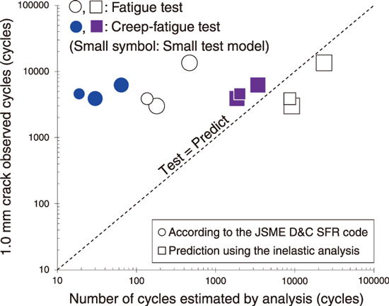
Fig.7-9 Failure prediction
Since the operating temperature, 550 ℃, of sodium fast reactors (SFRs) is much higher than that of light water reactors (around 300 ℃), and the temperature difference between the inlet and outlet of the reactor vessel is larger than that of light water reactors, the components of SFR are subjected to a cyclic thermal load due to thermal transitions during operation. Therefore, it is important to appropriately prevent failure due to cyclic thermal stress.
In the design of SFRs, the JSME (Japan Society of Mechanical Engineers) Code, Rules on Design and Construction for Nuclear Power Plants, Section II, SFR (the JSME D&C SFR code) is applied. To prevent failure by cyclic loads, the SFR code provides a rule regarding the creep-fatigue damage by considering the superimposition of creep and fatigue damage. Because of the difficulty in predicting the failure life by creep fatigue, the current rule is extremely conservative and should be improved.
In this study, cyclic loading tests with multiperforated plates were performed for confirming the conservativeness of the creep-fatigue damage limit rule in the JSME D&C SFR code and developing an evaluation method to predict the creep-fatigue life. We conducted fatigue and creep-fatigue tests, and finite element analysis simulating the tests were performed (Fig.7-7).
The elastic analysis used in conventional design and an inelastic analysis were performed. A material property setting guide had been constructed for the inelastic analysis. The inelastic analysis is not generally used in the design because of the difficulties in material parameter setting and calculation cost; however, it is expected to be applied to optimize the components design because it allows for more realistic simulations. The simulated result of the inelastic analysis indicated that the location where the maximum strain is generated corresponds to the crack initiation location (Fig.7-8).
According to the rule in the JSME D&C SFR code, the number of cycles corresponding to the limit of creep-fatigue damage was calculated from the elastic analysis result. The calculated result clarified that the limit has great conservativeness, though it includes the design margin. The predicted results of the inelastic analysis estimated the number of cycles corresponding to the crack initiation with good accuracy, and these results are expected to be a reference to improve the design procedure (Fig.7-9).
In the future, we plan to conduct various structural tests and their analytical evaluations to incorporate the inelastic analysis to the design rules.
(Masanori Ando)

