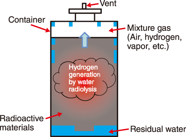
Fig.1 Interior of the radioactive waste storage container
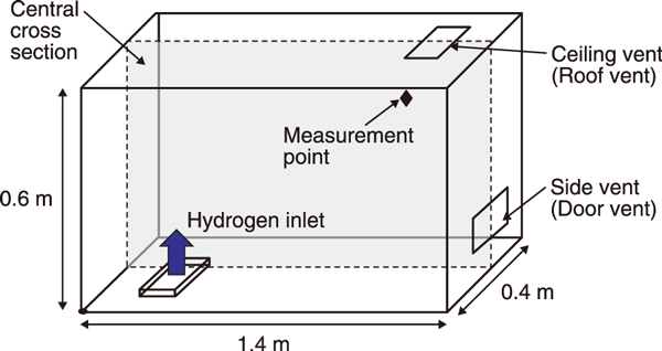
Fig.2 Room (model) for H2 leakage experiments
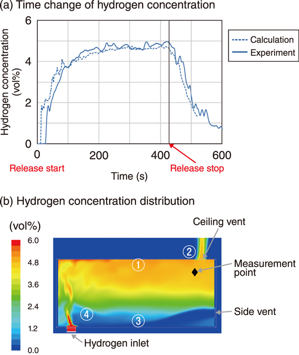
Fig.3 (a) Time change and (b) distribution of H2 concentration
As a part of the efforts toward recoverin from the accident at TEPCO’s Fukushima Daiichi Nuclear Power Station, we are conducting research and development (R&D) on the safe storage and management of radioactive waste such as fuel debris, which is scheduled for future retrieval.
Containers of radioactive waste are stored without water. If water remains in the container, radiation from the waste will decompose the water and generate hydrogen (H2), leading to the risk of combustion and explosion (Fig.1). Therefore, to prevent accumulation of H2 generated during storage, measures such as use of catalysts that return H2 to water and vents with filters that prevent the release of radioactive materials are being considered.
To validate these measures and develop new ones, we use numerical analysis and simulation methods called computational fluid dynamics (CFD) to study H2 leakage and diffusion. As an example of the study, we introduce the result of reproducing the H2 leakage experiment and further verifying the ventilation process.
In this study, vents were installed in the ceiling and on the side of the room (Fig.2), and H2 was discharged from the outlet at the bottom at a rate of 10 L/min for 420 s.
Fig.3 shows the (a) time change and (b) distribution of H2 concentration. The concentration at the measurement point (a) increased from the start of release and rapidly decreased after the end of release. From the perspective of H2 distribution in the room (b), when there is no wind outside the room, ① H2 from the outlet quickly reached the ceiling and ② was discharged through the ceiling vent. Simultaneously, ③ air flowed into the room from the side vent, and reached the outlet, resulting in low H2 concentration ④. When wind blew from right to left, the concentration decreased faster than in the case of no wind because the side vent was on the windward side. When the wind blew in the opposite direction, there was a concern that the concentration would be higher than in the case of no wind.
In the future, we will utilize such analysis and simulation techniques to clarify the behavior of H2 in the presence of water vapor and oxidants (e.g., NOx) and to work on the development of H2 retention prevention technology using a ventilation system that utilizes atmosphere control.
(Atsuhiko Terada)

