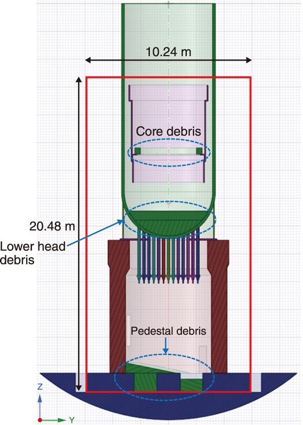
Fig.1 Target of the air-cooling simulation in FDNPS Unit 2
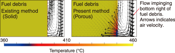
Fig.2 Comparison of conventional methods and porous media models
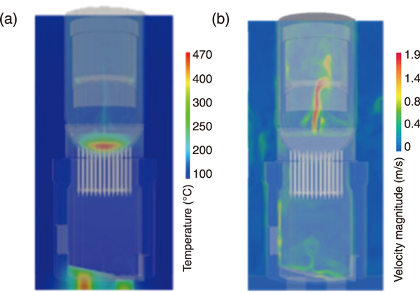
Fig.3 Temperature distribution of fuel debris (a) and air flow and its velocity distribution due to air cooling (b)
As a countermeasure for contaminated water generated during the decommissioning of the TEPCO’s Fukushima Daiichi Nuclear Power Station (FDNPS), it is essential to understand the thermal behavior of fuel debris under the coolant shutdown (air-cooled) condition. Knowledge of this behavior is critical during fuel debris retrieval. However, the on-site observation of the thermal behavior is difficult because of the high radiation dose at the site. Numerical simulation will be an effective method for understanding the circumstances in FDNPS. The JAEA has developed a numerical simulation method for estimating fuel debris temperature by air-cooling. This method yields more realistic results than the conventional method because unlike in the conventional methods, the numerical simulation method estimates fuel debris as a porous medium according to recent observation and analyses.
Using the developed method, air-cooling simulations were conducted for FDNPS Unit 2 assuming that heat-generating fuel debris exists in the core, lower plenum, and bottom of the pedestal inside the pressure vessel, as shown in Fig.1. Fig.2 shows the differences between the conventional method, which represents debris as a homogeneous solid, and the porous media model in terms of the temperature distribution. The figure shows that in the conventional method (left in Fig.2), air flow does not penetrate into the debris, but in the porous medium model, it penetrates into the debris and decreases the temperature.
Fig.3 shows the temperature (a) and speed distribution of fuel debris (b) in each region. Fig.3(a) shows that the temperature of the fuel debris in each region is higher than the temperature of the ambient atmosphere. In particular, the temperature of the lower plenum debris is the highest. Fig.3(b) shows the upward airflow from the lower plenum debris, and the complicated airflow and temperature distribution around the debris were also obtained. In the future, we plan to improve the reliability and applicability of this analysis method through verification by comparison with experimental results and by conducting analyses under various calculation models and conditions.
This research was conducted as a part of the subsidy for decommissioning and contaminated water countermeasures project, “Development of Analysis and Estimation Techniques for Determining the Properties of Fuel Debris,” supported by METI. The results of this research were obtained using the supercomputer HPE SGI8600 of the JAEA.
(Susumu Yamashita)

