 This picture, (95KB) |
||||
|
 |
||
|
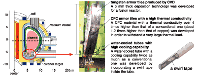
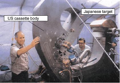
| In the course of the construction of ITER, it is one of the most important technologies to develop a heat-resistant divertor loaded with the influx of high-temperature plasma. Since the high-energy particles and heat of the plasma flow into the divertor, its heat flux becomes ten times higher than that of a fission reactor. In addition to the thermal load, a huge amount of repeated electro-magnetic forces load the divertor. So we should develop a new divertor satisfying ITER requirements by overcoming the above-mentioned difficulties. Four parties (Japan, USA, EU and the Russian Federation) conducted the development program of the divertor under the international collaboration. Each party performed the development of his identified field. JAERI developed a heat-resistant divertor target (shown in Fig. 2-17), which plasmas hit directly. The following results were obtained through the development. The newly developed components are (1) tungsten armor tiles produced by chemical vapor deposition (CVD) in order to reduce the sputtering yield, (2) a 3-dimensionally woven carbon-fiber-composite (CFC) with a thermal conductivity 4 times higher than that of a conventional CFC and 1.2 times higher than that of copper, (3) a water-cooled tube with a cooling capability twice as much as a conventional one by incorporating a swirl tape inside the tube, (4) a silver-free brazing material joining copper and tungsten or CFC in order to avoid the transmutation of silver to cadmium, and so on. A 1.3 m long full-scale mock-up, which was fabricated by assembling the developed components, survived 3,000 cycles at 5 MW/m2 for 30 s and, in addition, 1,000 cycles at 20 MW/m2 for 10 s. These thermal loads correspond to a lifetime of over 3 years in ITER. A full-scale mock-up was installed on a cassette body fabricated in the US (shown in Fig. 2-18). The test simulating the ITER operational scenario using the above test assembly verified that it satisfied the ITER design requirements. It is hoped the newly development technology is used in an industrial application of heat-resistance as well as in nuclear fusion. |
| Reference M. Ulrickson et al., The ITER Divertor Cassette Project, Fusion Energy 1998, IAEA, Vienna, IAEA-CSP-1/P, 1053 (1999). |
| Select a topic in left column |
|
Persistent Quest-Research Activities 2000 Copyright(c)Japan Atomic Energy Research Institute |