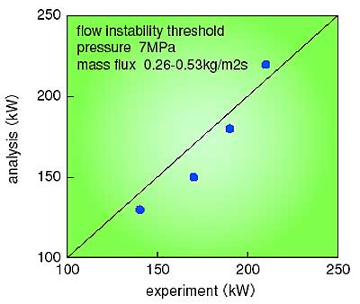
The TRAC/SKETCH code predicted well the THYNC experimental flow instability threshold results.
Thermal-hydraulic and neutronic dynamics are always interrelated in a BWR core. This influence is called thermal-neutronic coupling. Previously, reactor core data were used to verify the analysis method for flow stability under thermal-neutronic coupling. However, reactor in-core data are very limited due to the difficulty in making in-core measurements. Recently, advanced fuels, i.e., high-burnup fuels and MOX fuels, are planned for use in commercial plants. This necessitates improvement in stability analysis due to a narrower safety margin than with conventional fuels. Consequently, extensive thermal-hydraulic data under thermal-neutronic coupling conditions are needed.
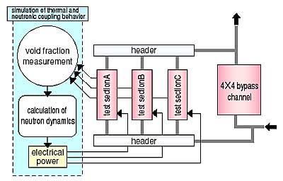
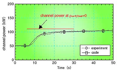
We have succeeded in experimentally simulating thermal-neutronic coupling under non-nuclear conditions with the THYNC facility. Fig. 1-4 shows a schematic diagram of the THYNC facility. It is important to measure the area-averaged void fraction with a high-response (100 ms response) void fraction meter. JAERI has developed a high-response, conductance-type void fraction meter, which operates under high-pressure and high-temperature conditions. Fig. 1-5 shows the experimental results that confirm the THYNC facility reasonably simulates thermal-neutronic coupling under non-nuclear conditions. Using the THYNC facility, significant quantities of data on the threshold of flow instability and cooling limits under flow oscillations were obtained.
The data obtained were used to study thermal-neutronic coupling effects on the instability threshold and cooling limits. The data were also used to demonstrate the prediction capability of the three-dimensional thermal-neutronic coupling code TRAC/SKETCH, which is under development in JAERI. As shown in Fig. 1-6, TRAC/SKETCH predicted the flow instability threshold well. This code was applied by the Nuclear Power Engineering Corporation for licensing calculations for a reactor using advanced fuels. |