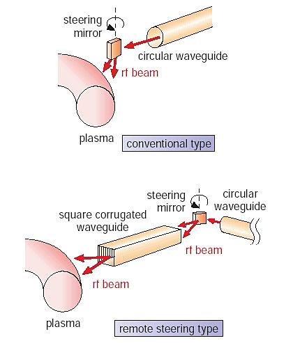
An electron cyclotron heating and current drive (ECH/CD) antenna for fusion plasma has a steering mirror placed close to the plasma, and the mirror controls the incident angle of the rf beams. This type of antenna is adopted in both JT-60 and ITER,. However, in a fusion reactor that will generate neutrons with a fluence ten times higher than ITER, the mirror would be damaged by the neutrons. To avoid this problem, a remote steering antenna that has no steering mirror in front has been developed. Schematic of two launcher concepts are shown in Fig. 2-16.
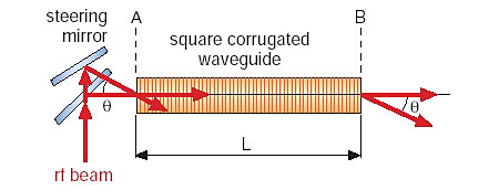
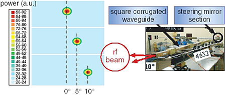
This antenna consists of a square corrugated waveguide that has corrugations on the inner wall and a steering mirror located at the inlet of the waveguide, i.e., far from the plasma. When a tilted Gaussian rf beam is injected into a square corrugated waveguide, many modes are excited and propagated within the waveguide. When the waveguide length is selected so the phase difference between the adjacent modes propagated in the waveguide is 2pi, the field distribution at the waveguide outlet is a reproduction of that at the inlet. That is, Gaussian rf beams can be radiated from the outlet in the same direction as those injected (Fig. 2-17). The prototype of the remote steering antenna (Fig. 2-18) was fabricated, and high-power rf (170 GHz, 0.5 MW) radiation experiments with the collaboration of US researchers confirmed the theory.
The experimental radiation pattern of Gaussian rf beams with incident angles toward the waveguide of 0°, 5°, and 10° are shown in Fig. 2-18. This demonstrates that the Gaussian rf beams are radiated as expected. The transmission loss in the waveguide was measured and found less than 5%. This experimentally confirmed the theory of the remote steering antenna and the capability of low-loss transmission. The results suggest the applicability of this antenna and the future prospect of utilization in fusion reactors.
|