Effective removal of "helium ash" from the reactor core is a very
important issue in sustaining stable fusion burning in a DT fusion
reactor as described in 2-1. Helium ash is DT reaction-born, high
energy helium ions slowed down to temperatures as low as those
of the fuel D-T ions after having heated the core plasma in a
fusion reactor. A method to use externally launched electromagnetic
waves in the ion cyclotron range of frequencies (ICRF) has been
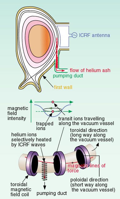
proposed. The idea is to heat helium ash ions selectively at the
plasma periphery by ICRF waves and drive the ions into a localized
area on the first wall by making good use of the spatial variation
of the toroidal magnetic field intensity (ripple of the toroidal
field), and exhaust them through pumping from the vacuum vessel.
Thus, helium ash accumulation in the reactor core can be avoided
(Fig. 2-5 (a)). In a tokamak geometry, the ripple field (or periodic
spatial variation of the toroidal field intensity near the plasma
periphery the long way along the doughnut-shaped vacuum vessel),
is formed because the toroidal magnetic field coils have to be
arranged at intervals along the vacuum vessel as shown in Fig.
2-5 (b).
We have performed a comprehensive and detailed numerical simulation
to study the feasibility of the above idea for the removal of
helium ash from a DT fusion reactor, using an orbit-following
Monte Carlo technique in a realistic tokamak geometry on an ITER-like
scale.
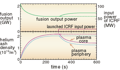
Figure 2-6 shows an example of the simulation results indicating
the effectiveness of this method. It is found that the suggested
mechanism for the removal of helium ash works well; the helium
ash density is reduced significantly by applying the proposed
scheme with a moderate input power (about 10 MW) of ICRF waves,
and consequently the fusion output recovers by about 300 MW as
shown in the figure. Because of the specific mechanism of this
method using ripple magnetic fields, helium ash is exhausted from
the main plasma in a specific direction to a spatially localized
area on the first wall of the vessel with a size of about 1.3
m by 0.7 m the long way and the short way along the doughnut-shaped
vacuum vessel, respectively. Since the issue of helium ash exhaust
is a crucial one in the R&D of a DT fusion reactor, further extended
studies are needed. |

