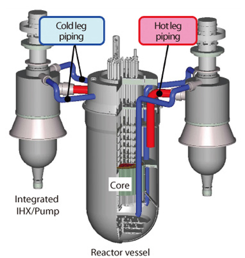
Fig.1-9 Schematic view of primary cooling system of JAEA sodium-cooled fast reactor (JSFR)

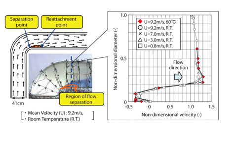
Fig.1-10 Flow pattern and velocity distributions in acrylic pipe

A JAEA sodium-cooled fast reactor (JSFR) is characterized by the use of a simplified two-looped large-scaled heat transport system as shown in Fig.1-9. As the results, the diameter of the piping system and the sodium flow velocity reach up to 1.3m and the order of 9.0m/s, respectively.
Generally, sodium-cooled fast reactors (FRs) use thin piping walls because of higher temperature and lower pressure operation conditions than light water reactors. JSFR operates with thin and larger diameter piping and higher flow velocity than conventional FR concepts. Therefore, maintaining structural integrity of the piping system is an important issue for the realization of the two-looped heat transport system, and vibration characteristics of the piping system, which is excited by turbulent flows generated at a 90° elbow, must be elucidated.
Addressing the above problems, water experiments on flow and vibration behavior of the piping system were carried out using a 1/3 scale model which simulates the hot leg piping of the primary cooling system. In this experiment, an acrylic pipe is used to visualize the flow pattern and a stainless steel pipe is used to simulate vibration response. As test parameters, mean velocity and water temperature, which are dominant factors affecting the flow condition, were selected; the dependencies of the flow conditions and vibration behavior were examined.
Firstly, flow pattern and the velocity distributions in the pipe were examined using the acrylic pipe (Fig.1-10). The region of flow separation, which becomes main source of the turbulent flows, was observed at the corner of the elbow. The sizes and locations of the region of flow separation and non-dimensional velocity distributions normalized by mean velocity almost coincided even in different velocity and water temperature conditions. Therefore, it was confirmed that flow pattern and velocity distributions in the piping were independent of flow conditions.
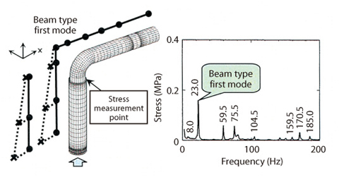
Next, the natural modes of vibration of the piping were identified using the steel pipe. Further, it was found that vibration stresses caused by turbulent flow were excited at the natural frequencies of the steel pipe (Fig.1-11).
From the test results, it was clarified that the turbulent flow and the vibration stress depended on the mean velocity. Then, the exciting force on the hot leg piping was characterized by converting the characteristics of the turbulent flow which were obtained in the acrylic pipe under the same velocity, based on the scale ratio, and the vibration response of the hot leg piping was evaluated. The maximum stress of the hot leg piping was below the design fatigue limit of the piping material, and therefore it is expected that the integrity of the large diameter piping will be maintained under high flow velocity condition.