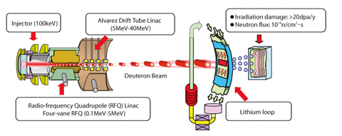
Fig.3-30 Configuration of International Fusion Materials Irradiation Facility (IFMIF)
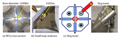
Fig.3-31 Photographs of RFQ mock-up modules
For the development of a demonstration fusion reactor, an evaluation of feasibility of fusion reactor materials using 14MeV neutron irradiation is indispensable. For this purpose, the International Fusion Materials Irradiation Facility (IFMIF) is being jointly planned by Japan, the European Union, the United States and the Russian Federation under the auspices of the IEA (International Energy Agency). In IFMIF, a neutron field is produced by the deuteron (d)-lithium(Li) stripping reaction. The realization of a deuteron beam that can be accelerated and injected into liquid lithium, is a key issue (Fig.3-30). In this accelerator facility, two beam lines of 125mA are used. CW operation is also required, making this the world's first attempt at developing such a high-current beam CW linac.
One beam line consists of an ion injector, an Radio-Frequency Quadrupole (RFQ) Linac and a Drift Tube Linac (DTL), their output energies are designed to be 0.1, 5.0 and 40.0 MeV, respectively. We developed a new RFQ, since the RFQ had many technical issues to be overcome for the realization of the high-current and CW operation in this configuration.
In this RFQ design, a lower operation frequency of 175MHz is used to accelerate to the high-current of 125mA. By this frequency, a world record 12.5m-long RFQ is needed, and extremely precise control of RF properties (RF power-balance and phase difference among all cavities) is required.
In this study, RF properties using a real size RFQ mock-up module (Fig.3-31) are evaluated to establish the precise control of RF properties. Specially, an important key element technology is a loop antenna to inject RF power into the RFQ. Deteriorations of phase differences caused by inserting the antenna are analyzed by a 3-D simulation code to determine the specifications of the antenna. The deterioration could be suppressed to less than a few degrees by suitably arranging four small loop antennas in the RFQ quadrants. The power-balance can be controlled and withstanding voltage can be also moderated, which is indispensable for CW operation. Additionally, slug tuners are fabricated to maintain the power-balance, compensating for fabrication errors of the 12.5m-long RFQ and positioning errors of the multi-loop antenna, and thus a key technology for power-balance control has been established. With these results, there are prospects for a development of the world's first 175MHz RFQ prototype with extremely precise control of RF properties