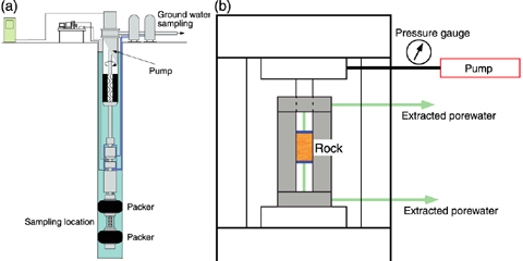
Fig.2-21 (a) Groundwater pumping system
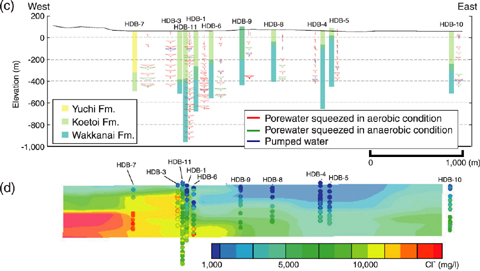
Fig.2-22 (c) Geological columns and Hexadiagram
In Japan, the high-level radioactive wastes (HLW) generated with the reprocessing of used fuels are planned to be disposed in the ground deeper than 300 meters. The groundwater will be pumped up during the construction and operation phase of the disposal facility. It is suggested that the geological environments around the facility will be changed. In this research, the techniques to estimate the distributions of groundwater chemistries from the ground level (GL) to about GL -500m before constructing the facility were developed.
The chemical data of meteoric water, river water, groundwater and porewater were used for the estimation. The chemical data of 18 groundwater and 170 porewater samples were analyzed (Fig.2-22(c)) during 11 borehole investigations (HDB-1 to HDB-11). The boreholes were Our research results show clearly that the bentonite fluid influences the groundwater chemistry. The groundwater was sampled in the hydraulic packer test (Fig.2-21(a)).
The porewater was extracted by squeezing in a suitably-designed high pressure cell. This technique has been successfully utilized by the British Geological Survey (BGS) in the Nirex site investigations (Fig.2-21(b)).
The inverse-distance interpolation method was applied to these data, and three dimensional distributions of groundwater chemistries have been estimated (Fig.2-22(d)). As the result, the distribution revealed a change in groundwater chemistry from the fresh water system (Na-HCO3 type) to saline water system (Na-Cl type) with increasing depth. It is understood that the boundary depth of the fresh water and saline water is different in the east and west portions of the area.
We will simulate and discuss the evolution process of these groundwater chemistries in the future. Also, the validity of this geochemical model will be confirmed by comparison with the groundwater chemistry changes during the construction and operation of the underground facility.