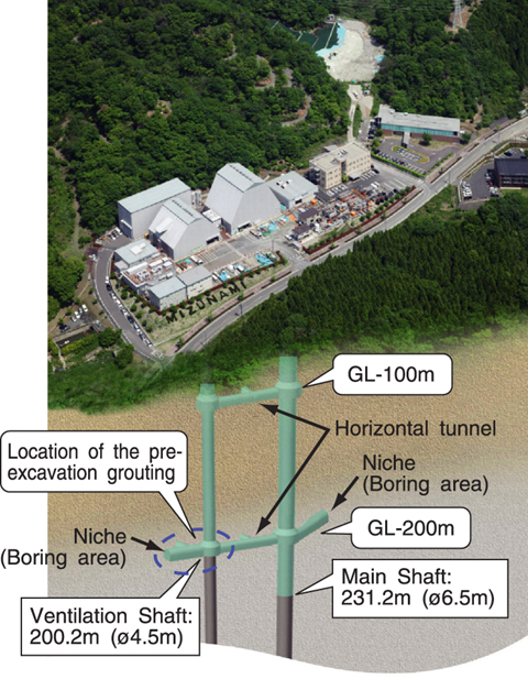
Fig.14-21 Image of the "Mizunami Underground Research Laboratory"
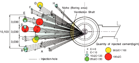
Fig.14-22 Quantity of injected cement per unit length of the pre-excavation grouting at the Ventilation Shaft niche (boring area)
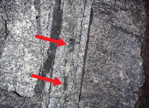
Fig.14-23 Photograph of cement filled fractures
The "Mizunami Underground Research Laboratory" (MIU), one of the main facilities in Japan for research and development of the technology for high-level radioactive waste disposal, is being constructed in Mizunami City. Excavation of shafts and galleries is being done to confirm the results of the predictions made in the surface-based investigation phase. As of March, 2008, the excavation of the Main and Ventilation Shafts had reached GL-231.2m and -200.2m (below ground level) (Fig.14-21). Optimization of the costs for treatment of the groundwater as well as reduction of the inflow water volume was required for continuing the MIU excavations. In planning the excavation of the shafts and tunnels below about GL-180m, it was necessary to get more reliable information on the conditions in terms of the rock mass stability and hydrogeology. Therefore, pilot borehole investigations were conducted from the bottom of the shafts. The results indicated that large water inflow could be expected during the excavation around the Ventilation Shaft and the Ventilation Shaft niche (boring area) at GL-200m. In order to reduce the drilling time, procedures for grout injection-hole drilling incorporated the use of a shaft jumbo (blast hole drilling rig) instead of a conventional borehole drill rig. This is one of the engineering techniques tried in the development of the construction procedures. As a result, it was possible for grouting to be accomplished within the planned excavation cycle. The two shafts were extended to GL-200m followed by pre-excavation grouting of the rock mass around the Ventilation Shaft and the planned Ventilation Shaft niche (Fig.14-21). Then, horizontal tunnels were excavated at that level. The pre-excavation grouting around the Ventilation Shaft niche is shown in Fig.14-22.
After the pre-excavation grouting and tunnel excavation, geological mapping was performed to determine the location and extent of the grout penetration. The geological mapping of the tunnels and walls confirmed the successful injection of a large volume of cement into the fractures. An example of a cement filled fracture in the Ventilation Shaft niche is shown in Fig.14-23. The inflow of water through the grouted rock mass was quite small. In areas with a large volume of injected cement, the inflow of water during the excavation was minimal. The grouting procedure using a shaft jumbo for drilling also resulted in a 6% decrease in the excavation cycle time, compared with the use of a conventional boring machine. Constant injection pressure during the last step in the grouting injection cycle prevented cement backflow from the fractures. Pre-excavation grouting will be the standard method for reducing the inflow of water. In this way, construction of the MIU can proceed, while minimizing the cost of water treatment by reducing the inflow of water.