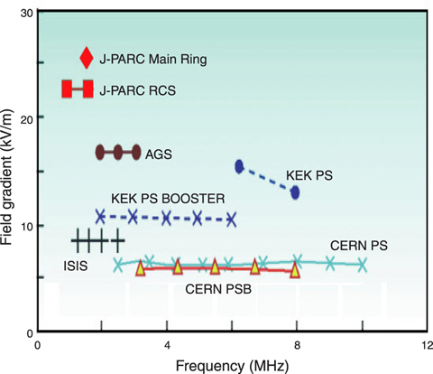
Fig.14-10 Field gradient of major proton synchrotrons in the world
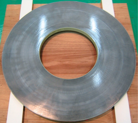
Fig.14-11 Magnetic Alloy core
J-PARC Rapid-Cycling Synchrotron (RCS) is one of the core facilities in J-PARC. In the RCS, a proton beam is accelerated up to 3GeV with high repetition rate of 25Hz. One of the most difficult challenges was how to achieve a field gradient of higher than 20kV/m in order to keep the RCS to a reasonable size. It is impossible to achieve such a high field gradient with conventional ferrite cores because the magnetic flux in the ferrite core reaches saturation level (Fig.14-10). Thanks to high saturation flux density of Magnetic Alloy (MA) cores, the RF cavity loaded with MA cores can generate the required field gradient and has the potential for higher gradients.
The material we chose for the MA core was a ribbon of amorphous metal composed mostly of iron. The MA cores are produced by winding ribbons with a thickness of about 18μm and width of 35mm. A coating of SiO2 with thickness of 2μm was put on one side of the MA ribbon to create electrical insulation (Fig.14-11).
We employ a direct water-cooling system for the RF cavity, and therefore the core surface was covered with epoxy coating to prevent rusting. The length of the rf cavity is about 2m and 18 MA cores are loaded in it.
In the development of MA core, we improved the core quality on the basis of the results of over 300 hours of high power tests. In the early stage of high power tests, we observed core damage and detachments of the epoxy coating from the core surface. Investigating the circumstances of the core damage, we found that they were caused by poor electrical insulation between ribbons. We improved the electrical insulation by optimizing the tension of the winding process of the ribbons in order to protect the SiO2 layer. To solve the problem of epoxy coating detachment, we impregnated epoxy resin inside the core, to improve the coating adhesion. In high power tests using these improved cores, we observed no core damage and no detachments of epoxy coating. Finally, we achieved the field gradient of 23kV/m, which was higher than our development target of 20kV/m.
We installed 10 RF cavities loaded with MA cores in the RCS in May 2007 and started beam commissioning in October 2007.

