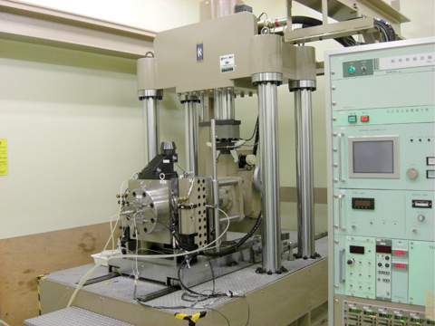
Fig.2-8 Laboratory 1:20 scale simulation test equipment
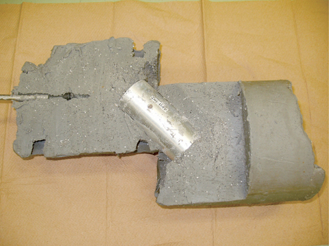
Fig.2-9 Sheared sample after test
Table 2-1 Shear test cases and experimental conditions
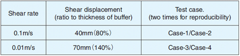
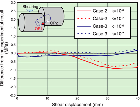
Fig.2-10 Comparison of calculated and observed data: total pressure against shear displacement
In the Japanese repository concept, high-level radioactive waste (HLW) is encapsulated in a steel overpack, which is surrounded by a bentonite clay buffer. The overpack is required to completely isolate the waste from human and his environment for at least 1,000 years.
In accordance with Japanese law, site selection of a HLW repository is being implemented in three steps. Currently, the national R&D program for HLW disposal is aiming to realize the 2nd phase, in which the Detailed Investigation Area will be selected based on a surface-based investigation, paying special care to avoid areas affected by fault movements. However, minor faults are difficult to identify and characterize from the surface, especially if they are at some depth. Thus, the size of impact a fault movement could have if it intersects the HLW repository is of great concern.
JAEA is now conducting experiments using laboratory 1:20 scale simulation test equipment (Fig.2-8). Based on previous hidden faults, the present study focused on fault movements with a displacement less than 1m and shear rates less than 1m/s. Due to the mechanical limits of the test equipment, the tests have to be conducted an order of magnitude below these values. It was therefore necessary to develop a numerical model in order to extrapolate results to the critical range.
Four test cases carried out under the conditions given in Table 2-1 resulted in no visible damage to or deformation of the overpack, although it rotated within the buffer (Fig.2-9). Numerical analysis was conducted with a three-dimensional, non-linear, finite element model. Through comparison with experimental results, it was found that the current numerical model can only estimate the impact on the system caused by fault movement displacement up to half of the buffer thickness (~20mm) (Fig.2-10). This showed the limitations of the finite element mesh model used. It is therefore crucial to further improve the model for confident extrapolation into the critical range, e.g. a model that includes contacting elements, which generate friction in sliding.

