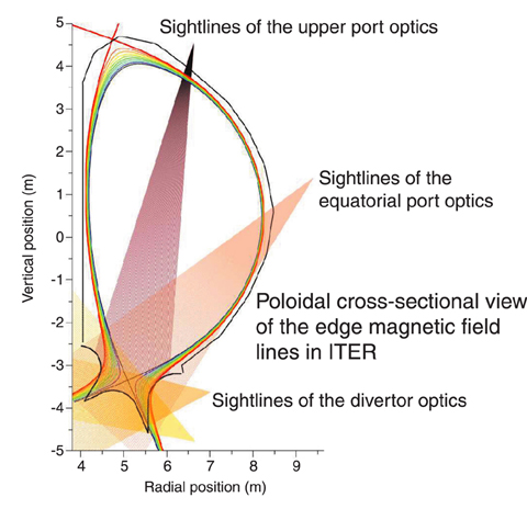
Fig.3-16 Sightlines of impurity influx monitor (divertor)
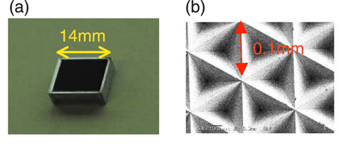
Fig.3-17 Micro retro-reflector array
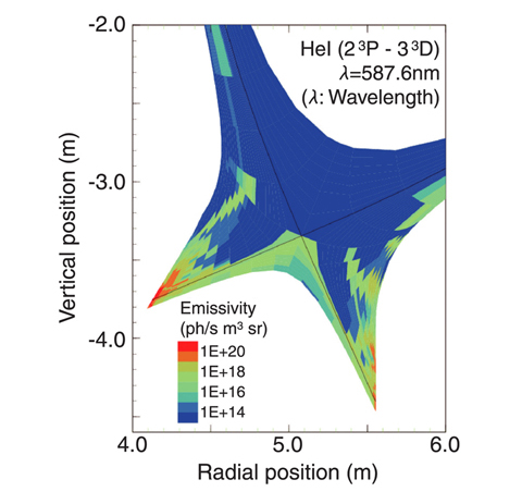
Fig.3-18 Helium atom spectral line emissivity of divertor (HeI:wavelength 587.6nm)
A nuclear fusion output of 500MW for 400s or longer is a primary objective for ITER. No current diagnostics systems are able to function in this harsh environment of high temperature, high radiation, and high particle flux. Such a system must be developed.
The main function of the Impurity Influx Monitor (divertor) shown in Fig.3-16 is to detect impurities and the isotopes of hydrogen (tritium, deuterium and hydrogen) in the divertor plasmas from their spectra in the wavelength range of 200 to 1000nm. The goal is to obtain valuable data indispensable for the control of impurities and of divertor plasma. To create this system, both design and R&D studies of optical systems with Mo mirrors, which are usable near the plasma, are being carried out.
A primary concern is that optical performance will deteriorate due to high temperature, high particle flux, and high radiation during operations, making it difficult to measure impurity influx to within a 10% accuracy level. Establishing an in-situ calibration method would allow the sensitivity of the optical system to be checked at any time. A new, in-situ calibration method applicable to ITER operations has been developed. Its key element is a micro retro-reflector array (MRRA) in which reflected light returns along the same optical path as incident light. The light introduced from outside passes to the further end of the optical system and is reflected by the MRRA set up there. Optical sensitivity is determined based on the strength of the light returning to the detector.
The MRRA is a compact arrangement of 0.1mm micro retro-reflectors shown in Fig.3-17. A full-scale MRRA has been constructed for the upper port optics, and testing of the array confirmed its applicability for ITER.
The helium generated by the fusion reaction flows to the divertor in ITER. The helium atom spectral line emissivity profile was evaluated using a collisional radiative model and an edge plasma model, as shown in Fig.3-18. A two-dimensional distribution can be calculated according to the observed line integration strength in the divertor region from two or more vantage points, as shown in Fig.3-16. Optimization of the positions of the side optics enables a spatial resolution of about 100mm. Results suggest that the fan array structure shown in Fig.3-16 allows an accurate determination of the complex emissivity profile shown in Fig.3-18.

