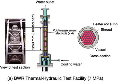
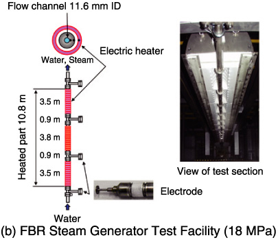
Fig.14-4 Test facilities applied to the capacitance void measurement method
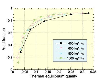
Fig.14-5 Result of void fraction measurement in BWR thermal hydraulic testing
In a Boiling Water Reactor (BWR), reactor power, fuel conversion ratio, and reactor cooling capacity change according to the void fraction in the core. We have developed a capacitance method (C method) to measure the void fraction under high temperature and high pressure conditions simulating those of a reactor. This C method is based on the principle that the capacitance in the two-phase flow is a function of the void fraction. Using this method, we can measure void fractions in real time, at all regions of void fractions, and with a small measurement error, which had not been realized by hitherto standard techniques.
From a calibration test of the C method using a quick shut valve, we found that the curve of capacitance vs. void fraction is represented by a fixed hyperbolic function, that this function can be applied to a high void fraction region, and that this function is uninfluenced by water quality. Furthermore, using an electrode insulator made of special ceramic material (with a thermal expansion coefficient equal to that of metal), we enabled C method measurements to be made up to 330 °C and 18 MPa.
We obtained void fraction data by applying the C method to the following tests.
(1) Thermal hydraulic test (Fig.14-4(a), Fig.14-5)
Development test for reduced moderation water reactor.
(2) BWR thermal hydraulics neutronics coupling test
Reactor stability test at 100% BWR output.
(3) Transient boiling test
Reactor safety test with reactivity induced by void fraction under sudden fuel rod heat. The method is based on the principle that capacitance in the two phase flow changes according to the void fraction.
(4) FBR steam generator test facility (Fig.14-4(b))
Flow instability test in a small pipe simulating the secondary loop of the FBR steam generator.
(5) Flow test for BWR plenum
Flow characteristics test in the upper plenum of the BWR core.
Void fraction measurement for micro channels was developed as an application of this method. The C method is expected to promote development of micro machines such as CPU small heat exchangers and so on.

