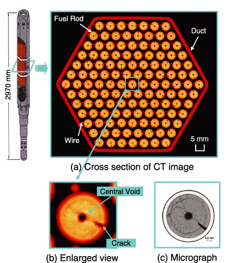
Fig.12-19 High-resolution computed tomography (CT) image of fuel assembly (upper) and enlarged view of fuel pellet (bottom)
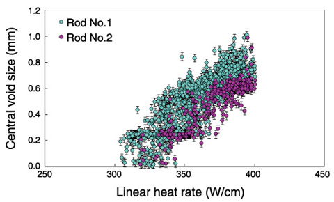
Fig.12-20 Formation of central void
In order to develop fast breeder reactor (FBR), it is important to investigate irradiation performance of FBR fuels and materials by Post Irradiation Examination (PIE). In the Fuel Monitoring Facility (FMF), non-destructive examination using the X-ray Computed Tomography (CT) technique was developed to observe irradiation performance of FBR fuel assembly and fuel rod.
In this study, the previous X-ray CT apparatus was upgraded to observe irradiation performance of the FBR fuel in the intact fuel assembly by using high resolution X-ray CT image. In order to obtain high resolution X-ray CT image, highly sensitive silicon semiconductor detectors (number of detector: 30→100) and a tungsten collimator with thin slits (width: 0.3 mm→0.1 mm, number of slits: 30→100) was installed in this X-ray CT apparatus. As a result, the one-pixel size of the CT image was reduced from 0.3 mm to 0.1 mm, and a high resolution X-ray CT image of the irradiated fuel assembly was obtained (Fig.12-19 (a)). The duct tube, fuel rods, wrapping wire, cladding, crack, and central void can be clearly observed in high resolution X-ray CT image (Fig.12-19 (a) (b)). In addition, the X-ray CT image gave almost the same results as those from the destructive examination (Fig.12-19 (c)).
In order to estimate the irradiation behavior of FBR fuel, the central void formed in fuel pellet was analyzed using this technology. Analysis results of central void size in the fuel pellet are shown in Fig.12-20. This figure shows that the central void was formed at more than about 300W/cm, and was dependent on the linear heat rate. Furthermore, this result shows that the central void size was affected by specification of fuel pellet. These results obtained using this technology can be applied to design FBR fuel.
This paper contains some results obtained within the task “Study of the irradiation behavior of the fuel pellets using the high-resolution X-ray CT technique” entrusted from the Ministry of Education, Culture, Sports, Science and Technology of Japan (MEXT).

