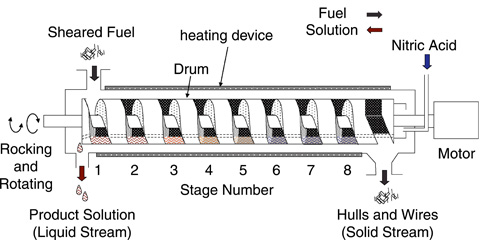
Fig.1-28 Schematic diagram of rotary drum type continuous dissolver
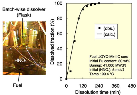
Fig.1-29 Dissolution behavior of FBR spent fuel in a batch-wise dissolver
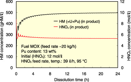
Fig.1-30 Calculation result for mixed oxide (MOX) fuel dissolution by rotary drum type continuous dissolver
As a part of the advance aqueous reprocessing technology for FBR fuel cycle, we have been developing rotary drum type continuous dissolver for FBR spent fuel dissolution (Fig.1-28). Some features of this dissolver make it preferable to the traditional batch-wise ones; these features include higher dissolution capacity with smaller apparatus size and the geometric advantage of a cylindrical drum with B4C installment at the drum center for criticality safety in the case of any concentration of fissile materials. In the rotary drum type continuous dissolver, effective fuel dissolution can be achieved by rocking the drum to achieve agitation and by counter flow of fuel and nitric acid. For estimating the fuel dissolution behavior under several operational conditions in this dissolver, we have been developing the simulation code for rotary drum type continuous dissolver.
This simulation code mainly consists of three modules: the first module is for evaluating chemical reaction, which considers the dissolution of UO2 fuel and FBR spent fuel (MOX fuel) with high Pu content; the second module is for calculating the mass balance, which also estimates the transfer of powdered fuel between stages by nitric acid flow and drum rocking; and the third module is for calculating the thermal balance in the dissolver surrounded by a heating device. This code can also simulate the fuel dissolution behavior in a batch-wise dissolver by regarding it as a single stage dissolver (Fig.1-29).
For the UO2 dissolution conditions in a rotary drum type continuous dissolver, the fuel dissolution behavior simulated by this code was in good agreement with the experimental one. The condition for obtaining the required dissolver solution was also analyzed using this code and appropriate operational conditions of the rotary drum type continuous dissolver, including appropriate feed rate, and concentration and temperature of nitric acid, could be clarified (Fig.1-30). We will continue to improve the simulation code for higher reliability and try to optimize the dissolution conditions by using the code.

