Fig.3-2 Configuration of TF coil
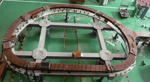
Fig.3-3 Insulated one-third-scale double pancake (5.1 m × 3.8 m)
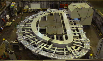
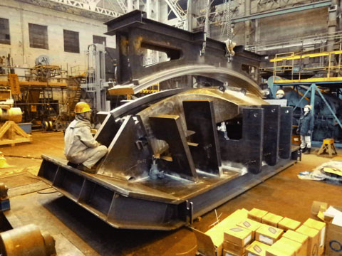
Fig.3-4 Full-scale radial plate (13 m × 8 m)
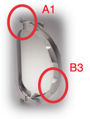
Mock-up trial of A1
Assembly of B3
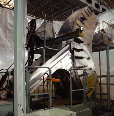
Fig.3-5 Full-scale segments of coil case
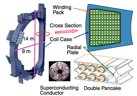
The superconducting (SC) coil system in the International Thermonuclear Experimental Reactor (ITER) confines the plasma and controls the plasma shape by generating high magnetic fields of more than 10 T. A toroidal field (TF) coil, which is one of the important components in the ITER p roject and the biggest SC coil in the world, is 14 m high, 9 m wide, and weighs 300 tons; it consists of a winding pack and a coil case (Fig.3-2). The winding pack is composed of seven double pancakes (DPs). In a DP, an SC conductor is inserted in the grooves of a D-shaped radial plate (RP). Nineteen TF coils, including one spare, will be fabricated in the project. We will procure nine coils and ten additional coil cases. We started mock-up trials for the TF coil in June 2010.
When winding the conductor, the dimensional accuracy of the winding is required to insert the wound conductor into the grooves of the RP. By trial fabrication of one-third-scale DP mock-ups, we could confirm that the developed automatic winding machine can efficiently control the accuracy (<0.006%) of windings of a dummy conductor and a SC conductor. One DP using an SC conductor was heat-treated to measure the deformation during heat treatment, and the data obtained were considered for the actual fabrication. The other DP using a dummy conductor was inserted into the RP, resin-impregnated (Fig.3-3), and cut for inspection. The effectiveness of the insulation technology was verified by the mock-up trial. A full-scale RP mock-up was fabricated (Fig.3-4) to evaluate the welding distortion.
Mock-ups of segments A1 and B3 of a coil case were fabricated to establish the fabrication technology (Fig.3-5). The main challenge in the fabrication of the coil case was to form a 260 mm deep weld on one side of the case. This problem was overcome by using narrow-gap automatic tungsten inert gas (TIG) welding. Welding distortion in the mock-ups was investigated to establish the weld procedure.
In the near future, we plan to fabricate a full-scale DP by using the fabricated full-scale RP and thus verify the effectiveness of the DP fabrication technology.
<Previous: 3 Nuclear Fusion Research and Development | Next: 3-2 >

