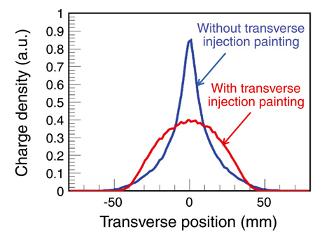
Fig.13-15 Transverse beam profiles obtained with and without transverse painting
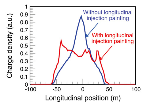
Fig.13-16 Longitudinal beam profiles obtained with and without longitudinal painting
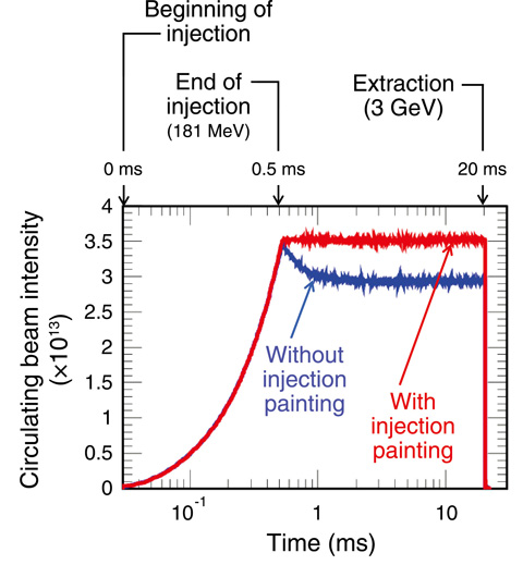
Fig.13-17 Beam loss observed for the 420 kW intensity beam with and without injection painting
The J-PARC Rapid Cycling Synchrotron (RCS) has two functions as a proton driver to produce pulsed muons and neutrons at the Materials and Life Science Experimental Facility and as an injector to the following Main Ring Synchrotron. RCS accelerates protons injected from the linac up to 3 GeV with a repetition rate of 25 Hz. Our final goal is to achieve 1 MW output beam power, which would be the highest level in the world.
The most important issues in increasing output beam power are the control and minimization of beam loss to maintain machine activation within the permissible level. There are many sources of beam loss, but the most critical one is the space-charge effect arising from Coulomb repulsive forces among beam particles. This effect is most serious at low energies. Therefore it causes beam loss just after injection. To alleviate this effect, RCS adopts an injection painting scheme, that reduces the charge density peak by distributing injected beam particles as uniformly as possible in both the transverse (direction at right angle to the beam orbit) and longitudinal (direction along the beam orbit) phase spaces. In transverse phase space, the injection beam is uniformly distributed by controlling the amplitude of betatron oscillation, namely by varying the phase-space offset between the centroid of the injection beam and the ring closed orbit during injection (0.5 ms), as shown in Fig.13-15. On the other hand, in longitudinal phase space, a uniform particle distribution is formed through emittance dilution by large synchrotron oscillation excited by a momentum offset during injection. By combining a dynamical control of the synchrotron potential well with the momentum offset injection scheme, the charge density peak in the longitudinal direction was significantly reduced, as shown in Fig.13-16. Using transverse and longitudinal injection painting, the large beam loss of 15%, observed for the 420 kW intensity beam, was successfully reduced to less than 1% , as shown in Fig.13-17.
At present, the injection energy is 181 MeV, but it will be upgraded to 400 MeV in 2013. After that, we will aim at our final goal of 1 MW output beam power. The above result achieved for the 420 kW intensity beam with an injection energy of 181 MeV is considered to be a big step toward realizing 1 MW design beam operation with the higher injection energy of 400 MeV, because the above two beam operations give an equivalent space-charge effect at each injection energy.

