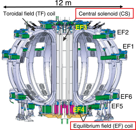
Fig.4-17 Superconducting coil system in JT-60SA
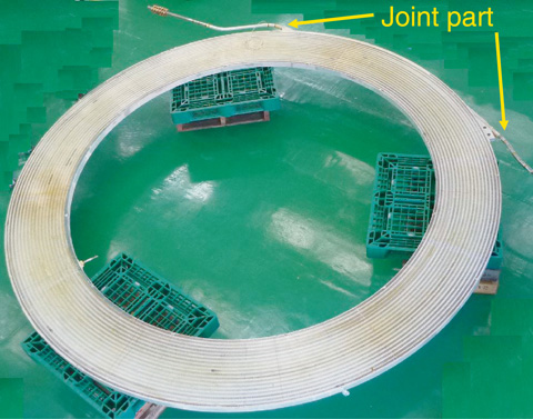
Fig.4-18 Double pancake coil for EF4
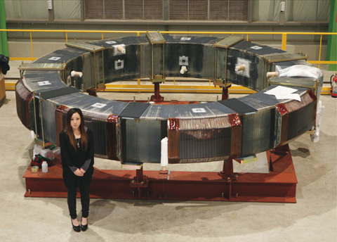
Fig.4-19 Winding pack for EF4 coil
Confinement of high-density, high-temperature plasmas for long durations is an important issue that must be resolved before the Tokamak fusion reactor is realized. For the long times needed for plasma control, the magnet system in JT-60SA is to be made of superconducting materials. A poloidal field (PF) coil system, which consists of a central solenoid (CS) and plasma equilibrium field (EF) coils, has been developed by JAEA (Fig.4-17). These coils are fabricated by stacking several pancake coils (Fig.4-18), and then connecting the conductor joints of the stacked pancake coils. The EF4 coil, the first superconducting coil in JT-60SA, consists of 10 double pancake (DP) coils.
To sustain high-performance plasmas, the configuration and position of the plasmas must be effectively controlled; this requires that the PF coil system must be manufactured with high precision. In particular, the EF4 coil forms the divertor configuration that needs to be sensitively controlled, and so errors in manufacturing the EF4 must be small compared to those for other coils. Simulation of plasma control shows that the required manufacturing error of circularity (in-plane ellipticity) in EF4 should be less than 6 mm. Measured errors of circularity for 10 DP coils, which makeup the EF4 coil, were no more than 3.8 mm. Circularity errors tend to be large around joint parts. Thus, joint parts were not gathered in a toroidal section; instead, they were toroidally distributed by each DP coil. By adopting this structure, circularity errors for the winding pack were averaged after stacking the DP coils. Therefore, for the EF4 winding pack, the circularity error was reduced to 0.6 mm (Fig.4-19). This is an order of magnitude smaller than the design requirements; this should reduce the strength of the error field, which limits precise control of the plasma.

